1
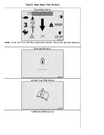
Operating
Screen
Password
Entry
Activity
Log
Calibration
Diagnostics
Truck
Setup
Truck
Status
Display
Adjustment
2
Operator Checklist
Load Weight
Add/Remove Password
VSM Version
Set Date and
Time Format
3
Impact Events
Manual Hydraulics
Restore Default
E-Steer Controller
1 Version
Set Units
4
Password
Steering Axle Center Point
E-Steer Controller
2 Version
Set Time
and Date
5
SHEET 1
Steering Axle Position
Impact Sensor
Version
Set Daylight
Saving Time
6
Steering Wheel Center Point
Light Controller
Version
7
Valve Threshold
Traction Motor
Controller 2
Version
8
Return to Set Tilt Stop
Traction Motor
Controller 1
Version
9
Pump Motor
Controller Version
10
E-Hydraulic
Controller Version
11
SHEET 2
Hour Meters
12
Truck Serial
Number
13
Display Version
14
Motion Alarm
15
Impact Monitor Settings
16
Auto Power-Off Time Delay
17
18
Return to Set Tilt
19
SHEET 3
Traction Speed Limit
20
Scheduled Maintenance
Required
21
Minimum Pump Standby
22
Operator Checklist
23
Interlock Menu Screen
Impact Monitor Shutdown
24
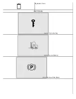
Cycle the
Key
Traction Switch
Direction Select in Neutral
Truck Disabled Due to Right
(Single) Traction Controller
25
Secure
Battery
Hydraulic Switch
Hydraulic Function 1 Out of Neutral
Truck Disabled Due to Left
Traction Controller
26
SHEET 4
Release
Park Brake
Temperature Too High
Hydraulic Function 2 Out of Neutral of
Function 2 Button Out of Neutral
Truck Disabled Due to Pump
Controller
27
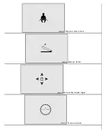
Operator
out of Seat
Lift Limit Exceeded
Hydraulic Function 3 Out of Neutral of
Function 3 Button Out of Neutral
Service Brake Interlock
28
Release
Accelerator
Charge Battery
Hydraulic Function 4 Out of Neutral of
Function 4 Button Out of Neutral
Motor Braking
29
Release
Hydraulic
Input
Impact Detected-Enter
Service/Supervisor
Password
Truck Disabled Due to E-Steer
Controller
Steering Wheel Friction and
Steering Turns Adjustment
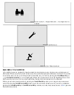
Menu Navigation
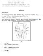
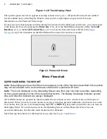
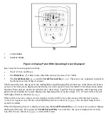
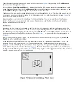
This topic explains how to use the keys on the Display Panel, shown in
, to navigate from one menu
to another and change settings.
Summary of Contents for ERC030VA
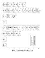
Page 8: ...Figure 3 Supervisor Flowchart Sheet 1 of 4 ...
Page 9: ...Figure 3 Supervisor Flowchart Sheet 2 of 4 ...
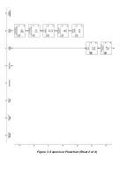
Page 10: ...Figure 3 Supervisor Flowchart Sheet 3 of 4 ...
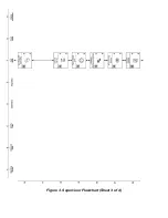
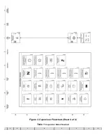
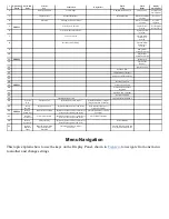
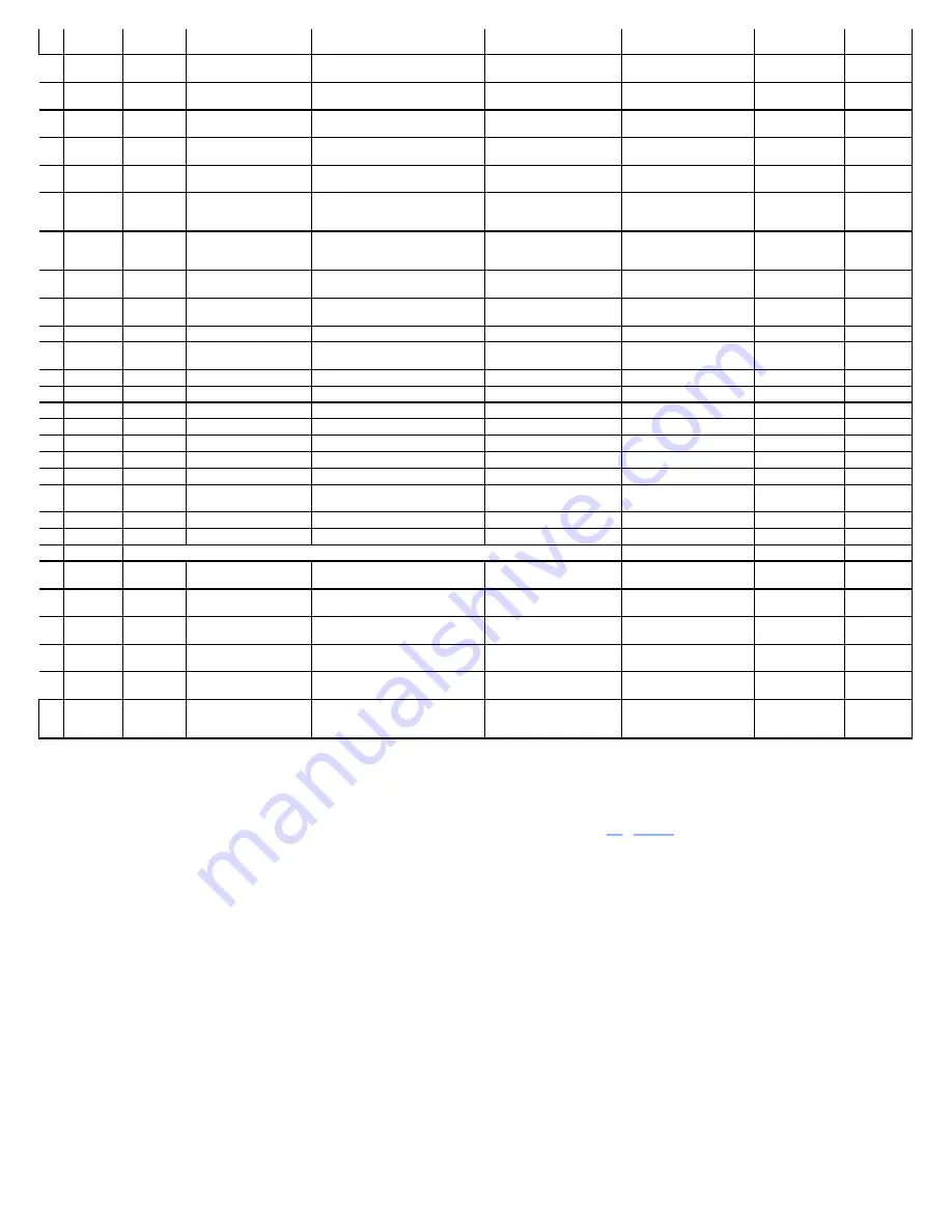
Page 11: ...Figure 3 Supervisor Flowchart Sheet 4 of 4 Table 1 Supervisor Menu Flowchart A B C D E F G H ...
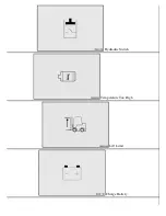
Page 21: ...Hydraulics Icon Alert Screens Cycle the Key Secure Battery Release Park Brake ...
Page 22: ...Operator Out of Seat Release Pedal Release Hydraulic Input Traction Switch ...
Page 23: ...Hydraulic Switch Temperature Too High Lift Limit Charge Battery ...
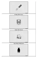
Page 26: ...Display Title Screen Status Title Screen Truck Setup Title Screen ...
Page 105: ...Figure 71 Steering Wheel Number of Turns Valid Entry ...


