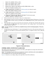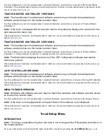
4
When prompted, turn the steering wheel clockwise until the axle hits the stop.
5
Press the
Enter Key
. If the settings are acceptable, the system records the steer positions and returns to
the Calibration Menu. If the settings are outside of the acceptable range, an X appears over the
calibration icon. Press the
Enter Key
and the system will prompt the user to repeat steps 2 – 5.
STEER AXLE CENTER POINT CALIBRATION
NOTE:
This calibration must be done by a supervisor or service technician and is only available on
trucks equipped with E-Steering.
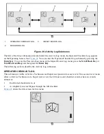
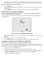
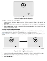
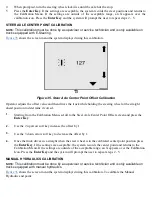
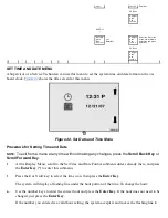
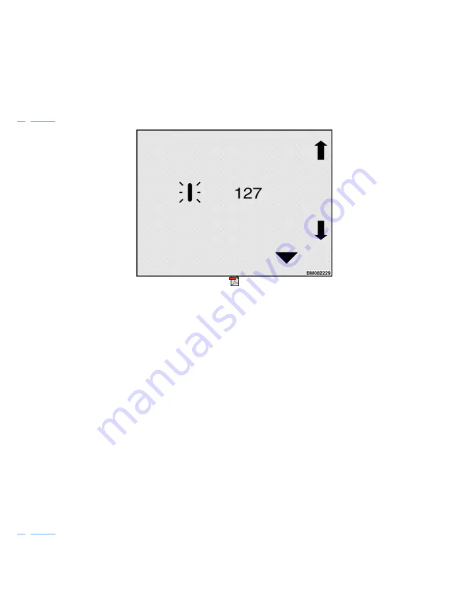
shows the screen menu the system displays during this calibration.
Figure 35. Steer Axle Center Point Offset Calibration
Operator adjusts the offset value and then drives the truck while holding the steering wheel at the straight
ahead position to determine if correct.
1.
Starting from the Calibration Menu, scroll to the Steer Axle Center Point Offset screen and press the
Enter Key
.
2.
Use the 2 up arrow soft key increase the offset by 1.
3.
Use the 3 down arrow soft key to decrease the offset by 1.
4.
Once the truck drives in a straight when the steer wheel is in the calibrated center point position press
the
Enter Key
. If the settings are acceptable, the system records the center point and returns to the
Calibration Menu. If the settings are outside of the acceptable range, an X appears over the Calibration
Icon. Press the
Enter Key
and the system will prompt the user to repeat steps 2 - 5.
MANUAL HYDRAULICS CALIBRATION
NOTE:
This calibration must be done by a supervisor or service technician and is only available on
trucks equipped with manual hydraulics.
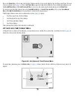
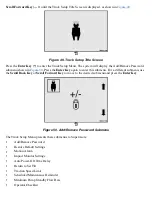
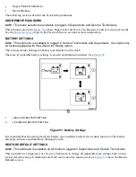
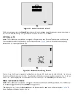
shows the screen menu the system displays during this calibration. To calibrate the Manual
Hydraulic end point:
Summary of Contents for ERC030VA
Page 8: ...Figure 3 Supervisor Flowchart Sheet 1 of 4 ...
Page 9: ...Figure 3 Supervisor Flowchart Sheet 2 of 4 ...
Page 10: ...Figure 3 Supervisor Flowchart Sheet 3 of 4 ...
Page 11: ...Figure 3 Supervisor Flowchart Sheet 4 of 4 Table 1 Supervisor Menu Flowchart A B C D E F G H ...
Page 21: ...Hydraulics Icon Alert Screens Cycle the Key Secure Battery Release Park Brake ...
Page 22: ...Operator Out of Seat Release Pedal Release Hydraulic Input Traction Switch ...
Page 23: ...Hydraulic Switch Temperature Too High Lift Limit Charge Battery ...
Page 26: ...Display Title Screen Status Title Screen Truck Setup Title Screen ...
Page 105: ...Figure 71 Steering Wheel Number of Turns Valid Entry ...

