background image

GP/GLP/GDP80VX, GP/GLP/GDP90VX, GP/GLP/GDP100VX, GP/GLP/

GDP110VX, GP/GLP/GDP120VX (J813)

SERVICE MANUAL CONTENTS

SECTION

PART

NUMBER

YRM

NUMBER

REV

DATE

FRAME............................................................................................................................

524262274  

0100 YRM 1243

05/14

OPERATOR'S CAB........................................................................................................

524306203  

0100 YRM 1290

04/14

GM 4.3L V-6 ENGINES...................................................................................................

524265337  

0600 YRM 1251

05/14

KUBOTA ENGINE REPAIR............................................................................................

550048607  

0600 YRM 1557

03/13

KUBOTA DIESEL 3.6L ENGINE....................................................................................

550055279  

0600 YRM 1579

01/14

COOLING SYSTEM........................................................................................................

524223757  

0700 YRM 1123

03/13

LPG FUEL SYSTEM GM 4.3L ENGINE WITH PSI........................................................

550043871  

0900 YRM 1556

04/14

GASOLINE FUEL SYSTEM............................................................................................

550048401  

0900 YRM 1570

09/13

1 AND 2 SP PS TRANSMISSION REPAIR....................................................................

550048681  

1300 YRM 1569

08/13

DRIVE AXLE AND DIFFERENTIAL ASSEMBLY REPAIR............................................

524262278  

1400 YRM 1246

12/13

DRIVE AXLE AND DIFFERENTIAL ASSEMBLY REPAIR............................................

550055280  

1400 YRM 1582

12/13

STEERING AXLE............................................................................................................

524223764  

1600 YRM 1133

07/13

WET BRAKES - NMHG..................................................................................................

550064329  

1800 YRM 1597

12/13

HYDRAULIC GEAR PUMP.............................................................................................

524223766  

1900 YRM 1136

04/14

HYDRAULIC CLEANLINESS PROCEDURES...............................................................

550073240  

1900 YRM 1620

12/14

MAIN CONTROL VALVE................................................................................................

524223767  

2000 YRM 1137

04/14

CYLINDER REPAIR (MAST S/N A551, A555, A559, A661, A662, A663, A66, B507,

B508, B509, B551, B555, B559, B562, B563, B564, B661, B662, B663, C515,

C551, C555, C559, D507, D508, D509, D515, D562, D563, D564, E509, AND

E564)..........................................................................................................................

524223768  

2100 YRM 1139

02/14

HIGH VOLTAGE SWITCH (HVS) IGNITION..................................................................

524208014  

2200 YRM 1097

05/14

WIRE HARNESS REPAIR..............................................................................................

524223769  

2200 YRM 1128

12/14

USER INTERFACE.........................................................................................................

524223770  

2200 YRM 1130

12/14

USER INTERFACE.........................................................................................................

524223771  

2200 YRM 1131

12/14

ELECTRICAL SYSTEM..................................................................................................

524223772  

2200 YRM 1142

04/14

MAST REPAIRS (S/N A513, A514, A613, A614, A702, A703, A704, A705, A706,

A707, A751, A752, B513, B514, B586, B587, B588, B589, B590, B591, B749,

B750, B751, B752, B753, B754)................................................................................

524265342  

4000 YRM 1250

02/14

METRIC AND INCH (SAE) FASTENERS.......................................................................

524150797  

8000 YRM 0231

10/13

CALIBRATION PROCEDURES......................................................................................

524223780  

8000 YRM 1134

12/14

DIAGRAMS AND SCHEMATICS....................................................................................

550055283  

8000 YRM 1585

04/14

PERIODIC MAINTENANCE............................................................................................

550068685  

8000 YRM 1604

12/13

CAPACITIES AND SPECIFICATIONS...........................................................................

550068693  

8000 YRM 1605

07/14

DIAGRAMS AND SCHEMATICS....................................................................................

550096331  

8000 YRM 1689

04/14

DIAGNOSTIC TROUBLESHOOTING MANUAL............................................................

524221866  

9000 YRM 1112

12/14

9000 YRM 1112 ON CD

PART NO. 550069027 (12/14)

Summary of Contents for GDP100VX

Page 1: ...0 YRM 1620 12 14 MAIN CONTROL VALVE 524223767 2000 YRM 1137 04 14 CYLINDER REPAIR MAST S N A551 A555 A559 A661 A662 A663 A66 B507 B508 B509 B551 B555 B559 B562 B563 B564 B661 B662 B663 C515 C551 C555 C559 D507 D508 D509 D515 D562 D563 D564 E509 AND E564 524223768 2100 YRM 1139 02 14 HIGH VOLTAGE SWITCH HVS IGNITION 524208014 2200 YRM 1097 05 14 WIRE HARNESS REPAIR 524223769 2200 YRM 1128 12 14 USE...

Page 2: ...odic Maintenance section Keep the unit clean and the working area clean and orderly Use the correct tools for the job Keep the tools clean and in good condition Always use YALE APPROVED parts when making repairs Replacement parts must meet or exceed the specifications of the original equipment manufacturer Make sure all nuts bolts snap rings and other fastening devices are removed before using for...

Page 3: ...3 24 Overhead Guard Replacement 25 Remove 25 Install 25 LED Tail Backup and Brake Lights Replace 26 Operator Restraint System Replacement 26 Description 26 Engine Replacement 28 Remove Engine Only 28 Install Engine only 56 Remove Engine and Transmission 60 Install Engine and Transmission 65 Electronic Throttle Replacement 69 Cummins 4 5L Diesel Engine With Electronic Throttle 69 Remove 69 Install ...

Page 4: ...VX J813 84 Remove 84 Inspect 87 Diesel Particulate Filter 89 Disassemble 89 CLEAN AND INSPECT 90 Assembly 91 Install 91 Cooling System 92 Description 92 Hydraulic Filter Assembly Repair 93 Remove 93 Disassemble 93 Clean 94 Inspect 94 Assemble 94 Install 94 Fuel and Hydraulic Tanks Repair 94 Inspect 94 Clean 95 Steam Method of Cleaning 95 Chemical Solution Method of Cleaning 96 Additional Preparati...

Page 5: ...See the procedure How to Put Lift Truck on Blocks in the Operating Manual or the Periodic Maintenance section for your lift truck If additional engine repairs are necessary for lift trucks covered in this manual see GM 4 3L V 6 Engines 0600YRM1251 Kubota Diesel 3 8L Engines 0600YRM1557 Kubota Diesel 3 6L Engine 0600YRM1579 If additional transmission repairs are necessary for lift trucks covered in...

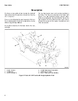
Page 6: ...e coun terweight The overhead guard cowl and hood are installed on the frame The hood is connected to the frame with hinges Two gas controlled springs provide assis tance when raising the hood and hold the hood in the open position The floor plate and side covers can be removed for access to the engine transmission and other components 1 COWL PLATE 2 FENDERS 3 HOOD MOUNTS 4 COUNTERWEIGHT MOUNTS 5 ...

Page 7: ...1 COWL PLATE 2 FENDERS 3 HOOD MOUNTS 4 COUNTERWEIGHT MOUNTS 5 HYDRAULIC TANKS Figure 2 Frame for Lift Trucks with Dual Hydraulic Tanks 0100 YRM 1243 Description 3 ...

Page 8: ...e capscrews Damage can be caused to the threads on the screws and in the holes 15 If seat is to be removed and truck is equipped with a non swivel seat remove seat wire harness from seat wire harness brackets that are attached to the underside of hood Remove the cable clips from the seat wire harness If truck is equipped with a swivel seat remove seat wire harness from seat wire harness bracket at...

Page 9: ...SEAT WIRE HARNESS CONNECTOR 6 CABLE CLIPS 7 HINGE SCREWS 8 GAS SPRING 9 ATTACHMENT HOLES ATTACHING HOOD TO SEAT SEMI SUSPENSION 10 SEAT WIRE HARNESS BRACKETS 11 SEAT LINER 12 HOOD LATCH 13 ATTACHMENT HOLES ATTACHING HOOD TO SEAT NON SUSPENSION 14 ATTACHMENT HOLES ATTACHING HOOD TO SEAT FULL SUSPENSION 15 SPACER 16 FLANGE NUT Figure 3 Hood and Seat Arrangement 0100 YRM 1243 Hood Seat and Side Cover...

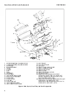
Page 10: ...0 LEFT STEP PLATE 21 LOCK NUT 22 RIGHT FRONT SIDE COVER 23 RIGHT FENDER COVER 24 RIGHT STEP PLATE 25 RIGHT PANEL 26 RIGHT REAR SIDE COVER 27 SPLASH SHIELD 28 RADIATOR COVER GLC40 45 55VX GLC55SVX GC GLC080 100 120VX GC GLC080 100VXBCS GC GLC120SVX GC GLC120VXPRS E818 F818 29 RADIATOR COVER GLP GDP40VX5 VX6 GLP GDP45SVX5 GLP GDP45VX6 GLP GDP50 55VX GP GLP GDP080 090 100 110 120VX F813 G813 H813 J81...

Page 11: ... OF DASH SHOWN A INDICATES TO PULL UP TO UNLATCH 1 ALLEN SCREWS 2 COWL 3 UPPER STEERING COLUMN COVER 4 LOWER STEERING COLUMN COVER Figure 5 Remove Dash From Cowl 0100 YRM 1243 Hood Seat and Side Covers Replacement 7 ...

Page 12: ...1 CAPSCREWS 2 SEAL PLATE Figure 6 Remove Seal Plate From Dash Hood Seat and Side Covers Replacement 0100 YRM 1243 8 ...

Page 13: ...Figure 7 Gas Spring Installation 0100 YRM 1243 Hood Seat and Side Covers Replacement 9 ...

Page 14: ...OR CYLINDER END OF GAS SPRING FOR SEMI OR FULL SUSPENSION SEAT Table 1 Gas Spring Installation Holes for Installing Rod Ends See Figure 7 Counterweight Type Full or Semi Suspension Seat Non Suspension Seat Left Side Right Side Left Side Right Side Standard Counterweight GLC40 45 50 55VX GC GLC080 100 120VX E818 F818 3 3 1 1 Standard Counterweight GLP GDP40VX5 VX6 GLP GDP45SVX5 GLP GDP45VX6 GLP GDP...

Page 15: ...ds on the screws and in the holes 7 Place seat on the hood and thread seat wire har ness through the hole in the hood See Figure 3 8 Align holes in the seat with the holes in hood In sert washers and capscrews Tighten capscrews to 18 N m 159 lbf in 9 If truck is equipped with a non swivel seat tie ca ble clips to seat wire harness and insert harness into seat wire harness brackets under hood If tr...

Page 16: ...DIESEL SHOWN LPG AND GAS SIMILAR 1 STEERING WHEEL 2 STEERING COLUMN 3 COWL Figure 9 Steering Column and Cowl 2 Attach a tag on battery connector or negative bat tery cable stating DO NOT CONNECT BAT TERY Move steering column to most FORWARD position CAUTION If a puller tool is used to remove steering wheel from steering column be careful not to damage horn wires NOTE This procedure is for removal ...

Page 17: ...ivot bolts two bushings two nuts and bracket from housing See Figure 12 for lift trucks manufactured before January 2012 See Figure 13 for lift trucks manufactured after January 2012 3 Remove split pin and lower shaft from upper shaft See Figure 12 for lift trucks manufactured before January 2012 See Figure 13 for lift trucks manufactured after January 2012 4 Remove connector from connector bracke...

Page 18: ...Figure 12 Steering Column Assembly Lift Trucks Manufactured Before January 2012 Steering Column 0100 YRM 1243 14 ...

Page 19: ...BOLT 11 BUSHING 12 NUT 13 GAS SPRING 14 BRACKET 15 CONNECTOR 1 BRACKET 2 SPACER 3 JOINT 4 NUT 5 WASHER 6 SCREW 7 UPPER SHAFT 8 HOUSING 9 PIN 10 LOWER SHAFT 11 GAS SPRING 12 BOLT 13 BUSHING 14 CONNECTOR 15 FASTENER 16 HORN CONTACT Figure 13 Steering Column Assembly Lift Trucks Manufactured After January 2012 0100 YRM 1243 Steering Column 15 ...

Page 20: ...gure 12 for lift trucks manufactured before January 2012 See Figure 13 for lift trucks manufactured after January 2012 3 Assemble lower shaft and upper shaft secure with spit pin See Figure 12 for lift trucks manufactured before January 2012 See Figure 13 for lift trucks manufactured after January 2012 4 Install two pivot bolts two bushings two nuts and bracket onto housing See Figure 12 for lift ...

Page 21: ...urface must be solid even and level when the lift truck is put on blocks Make sure that any blocks used to support the lift truck are solid onepiece units See the procedure How to Put Lift Truck on Blocks in the Operating Manual or the Periodic Maintenance section for your lift truck WARNING DO NOT operate the lift truck if the capscrew for the counterweight is not installed When the cap screw is ...

Page 22: ...813 G813 LPG Fuel System GM 4 3L Engine With PSI 900 YRM 1556 for lift truck models GLC40 45 55VX GLC55SVX GLC080 100 120VX GLC080 100VXBCS GLC120SVX GLC120VXPRS E818 F818 GLP40VX5 VX6 GLP45SVX5 GLP45VX6 GLP50 55VX GLP080 90 100 110 120VX G813 H813 J813 WARNING The counterweight is heavy Make sure that the eyebolt and lifting devices have enough capacity to lift the weight The approximate weights ...

Page 23: ...0XVBCS GC GLC100VXBCS GC GLC120SVX AND GC GLC120VXPRS E818 F818 LIFT TRUCK MODELS C COUNTERWEIGHT USED ON GLC40 45 55VX GC GLC080 100 120VX E818 F818 AND GLP GDP40VX5 VX6 GLP GDP45SVX5 GLP GDP45VX6 GLP GDP50 55VX GP GLP GDP080 090 100 110 120VX J813 LIFT TRUCK MODELS 1 FRAME HOOK 2 SEAL 3 LIFT HOLE 4 TOW PIN 5 ROLL PIN 6 WASHERS 7 CAPSCREW 8 WIRE 9 O RING Figure 14 Counterweight Installation 0100 ...

Page 24: ...6 GLP50 55VX GLP080 90 100 110 120VX J813 2 Use a crane to install counterweight on lift truck When counterweight is installed make sure hooks on frame fully engage counterweight so it is aligned with parts of frame Install and tighten capscrew to 1020 N m 750 lbf ft 3 Install tow pin and roll pin if equipped See sec tion Tow Pin for procedures 4 If lift truck has an LPG fuel system see one of the...

Page 25: ...N 7 ROLL PIN Figure 15 Counterweight Components for Lift Truck Models GLC40 45 55VX GC GLC080 100 120VX E818 F818 and GLP GDP40VX5 VX6 GLP GDP45SVX5 GLP GDP45VX6 GLP GDP50 55VX GP GLP GDP080 090 100 110 120VX F813 G813 H813 0100 YRM 1243 Counterweight Replacement 21 ...

Page 26: ...REW 2 WASHER 3 COUNTERWEIGHT 4 SEAL Figure 16 Counterweight Components for Lift Truck Models GLC55SVX GC GLC080 100VXBCS GC GLC GDC120SVX GC GLC GDC120VXPRS E818 F818 Counterweight Replacement 0100 YRM 1243 22 ...

Page 27: ...3 TOW PIN 4 WASHER 5 CAPSCREW Figure 17 Counterweight Components for Lift Truck Models GLP GDP40VX5 VX6 GLP GDP45SVX5 GLP GDP45VX6 GLP GDP50 55VX GP GLP GDP080 090 100 110 120VX J813 0100 YRM 1243 Counterweight Replacement 23 ...

Page 28: ...LL PIN Figure 18 Tow Pin Remove and Install For Lift Truck Models GLC55SVX GC GLC80XVBCS GC GLC100VXBCS GC GLC120SVX and GC GLC120VXPRS E818 F818 and GLP GDP40VX5 VX6 GLP GDP45SVX5 GLP GDP45VX6 GLP GDP50 55VX GP GLP GDP080 090 100 110 120VX J813 1 Remove tow pin from counterweight by grasping wire and pulling tow pin from counterweight See Figure 19 2 Install tow pin into counterweight dropping to...

Page 29: ...er head guard is off balance lower immediately and move hoist to a more centered point 1 Connect a lifting device to remove overhead guard Loosen clamp and disconnect air intake hose from elbow Remove bolts elbow retainer and grommet from overhead guard rear leg See Figure 20 2 Disconnect wires between frame and overhead guard When overhead guard is lifted from frame make sure that electrical wire...

Page 30: ...brackets seat and mount ing hood and latches are all part of operator restraint system Each item must be checked to make sure it is attached securely functions correctly and is in good condition See Figure 22 The seat belt when properly buckled across operator will permit slight operator repositioning without activat ing locking mechanism If truck tips travels off a dock or comes to a sudden stop ...

Page 31: ... when it is pulled with a sudden jerk replace seat belt as sembly With hood in open position make sure seat belt will not pull from retractor assembly If seat belt can be pulled from retractor with hood in open position replace seat belt assembly Make sure seat rails and latch striker are not loose The seat rails must lock tightly in position but move freely when unlocked The seat rails must be co...

Page 32: ...RNING LPG can cause an explosion DO NOT cause sparks or permit flammable material near the LPG system LPG fuel systems can be disconnected indoors only if the lift truck is at least 8 m 26 ft from any open flame motor vehicles electrical equipments or ignition source 1 For lift trucks equipped with an LPG fuel system close shutoff valve on tank and run engine until all fuel is gone and engine stop...

Page 33: ...2 TRANSMISSION MOUNTING BRACKET 3 ENGINE MOUNTING BRACKET 4 ENGINE CROSSMEMBER 5 ENGINE ISOLATOR ASSEMBLY 6 FRAME 7 ENGINE HARNESS CONNECTOR 8 LEFT CHASSIS WIRING HARNESS CONNEC TOR Figure 23 Engine and Transmission Mounting Arrangement for GM4 3L Engines Cummins 4 5L Diesel Engines and Cummins QSB 3 3L Diesel Engines 0100 YRM 1243 Engine Replacement 29 ...

Page 34: ...INE FOR LIFT TRUCK MODELS GLP GDP40VX5 VX6 GLP GDP45SVX5 GLP GDP45VX6 GLP GDP50 55VX GP GLP GDP080 090 100 110 120VX J813 C KUBOTA 3 6L DIESEL ENGINE 1 TRANSMISSION ISOLATOR ASSEMBLY 2 TRANSMISSION MOUNTING BRACKET 3 ENGINE ISOLATOR ASSEMBLY 4 ENGINE MOUNTING BRACKET 5 ENGINE HARNESS CONNECTOR 6 FRAME Figure 24 Engine and Transmission Mounting Arrangement for Kubota Engines Engine Replacement 0100...

Page 35: ...DP080 090 100 110 120VX H813 equipped with a Ku bota 3 8L diesel engine manufactured after Febru ary 2012 See Figure 30 for lift truck models GLP GDP40VX5 VX6 GLP GDP45SVX5 GLP GDP45VX6 GLP GDP50 55VX GP GLP GDP080 090 100 110 120VX J813 equipped with a Ku bota 3 8L diesel engine See Figure 31 for lift trucks models GLP GDP40VX5 VX6 GLP GDP45SVX5 GLP GDP45VX6 GLP GDP50 55VX GP GLP GDP080 090 100 1...

Page 36: ...Figure 25 GM 4 3L LPG Engine and Transmission with Single Hydraulic Tank Engine Replacement 0100 YRM 1243 32 ...

Page 37: ...GHT HAND CHASSIS HARNESS 8 ELECTRONIC CONTROL MODULE ECM 9 POWER DISTRIBUTION MODULE PDM 10 BATTERY AND BATTERY TRAY 11 COOLANT HOSES 12 FAN PULLEY AND FAN SPACER 13 FAN 14 SHROUD 15 EXHAUST PIPE TO EXHAUST MANIFOLD 16 FUEL LINES 17 RADIATOR CAP 18 TRANSMISSION MOUNT 19 BRAKE COOLING LINES 20 BATTERY CABLE POSITIVE 21 BATTERY CABLE NEGATIVE 22 HYDRAULIC RETURN HOSE 23 TRANSMISSION OIL COOLER LINES...

Page 38: ...Figure 26 GM 4 3L LPG Engine and Transmission with Dual Hydraulic Tanks Engine Replacement 0100 YRM 1243 34 ...

Page 39: ...NESS 8 ELECTRONIC CONTROL MODULE ECM 9 POWER DISTRIBUTION MODULE PDM 10 BATTERY AND BATTERY TRAY 11 COOLANT HOSES 12 FAN PULLEY AND FAN SPACER 13 FAN 14 SHROUD 15 EXHAUST PIPE TO EXHAUST MANIFOLD 16 FUEL LINES 17 RADIATOR CAP 18 TRANSMISSION MOUNT 19 BRAKE COOLING LINES 20 BATTERY CABLE POSITIVE 21 BATTERY CABLE NEGATIVE 22 HYDRAULIC RETURN HOSE 23 TRANSMISSION OIL COOLER LINES 24 HYDRAULIC SUPPLY...

Page 40: ...Figure 27 Cummins QSB 3 3L Diesel Engine and Transmission Engine Replacement 0100 YRM 1243 36 ...

Page 41: ...MOUNTING BRACKETS 8 FUEL LINES 9 ENGINE HARNESS CONNECTOR 10 BRAKE COOLING LINE 11 HYDRAULIC SUPPLY LINE 12 TRANSMISSION MOUNTING BRACKET 13 ELECTRONIC CONTROL MODULE 14 RIGHT HAND ENGINE HARNESS 15 HYDRAULIC RETURN LINE 16 BATTERY AND BATTERY TRAY 17 BATTERY CABLE POSITIVE 18 BATTERY CABLE NEGATIVE 19 FAN SPACER AND FAN PULLEY 20 CHARGE AIR HOSE 0100 YRM 1243 Engine Replacement 37 ...

Page 42: ... 3 8L Engine and Transmission for Lift Truck Models GLP GDP40VX5 VX6 GLP GDP45SVX5 GLP GDP45VX6 GLP GDP50 55VX GP GLP GDP080 090 100 110 120VX H813 Manufactured Before February 2012 Engine Replacement 0100 YRM 1243 38 ...

Page 43: ...7 ENGINE MOUNTING BRACKETS 8 FUEL LINES 9 ENGINE HARNESS CONNECTOR 10 BRAKE COOLING LINE 11 HYDRAULIC SUPPLY LINE 12 TRANSMISSION MOUNTING BRACKET 13 ELECTRONIC CONTROL MODULE 14 RIGHT HAND ENGINE HARNESS 15 HYDRAULIC RETURN LINE 16 BATTERY AND BATTERY TRAY 17 BATTERY CABLE POSITIVE 18 BATTERY CABLE NEGATIVE 19 FAN SPACER AND FAN PULLEY 0100 YRM 1243 Engine Replacement 39 ...

Page 44: ...a 3 8L Engine and Transmission for Lift Truck Models GLP GDP40VX5 VX6 GLP GDP45SVX5 GLP GDP45VX6 GLP GDP50 55VX GP GLP GDP080 090 100 110 120VX H813 Manufactured After February 2012 Engine Replacement 0100 YRM 1243 40 ...

Page 45: ...7 ENGINE MOUNTING BRACKETS 8 FUEL LINES 9 ENGINE HARNESS CONNECTOR 10 BRAKE COOLING LINE 11 HYDRAULIC SUPPLY LINE 12 TRANSMISSION MOUNTING BRACKET 13 ELECTRONIC CONTROL MODULE 14 RIGHT HAND ENGINE HARNESS 15 HYDRAULIC RETURN LINE 16 BATTERY AND BATTERY TRAY 17 BATTERY CABLE POSITIVE 18 BATTERY CABLE NEGATIVE 19 FAN SPACER AND FAN PULLEY 0100 YRM 1243 Engine Replacement 41 ...

Page 46: ...Figure 30 Kubota 3 8L Engine and Transmission for Lift Truck Models GLP GDP40VX5 VX6 GLP GDP45SVX5 GLP GDP45VX6 GLP GDP50 55VX GP GLP GDP080 090 100 110 120VX J813 Engine Replacement 0100 YRM 1243 42 ...

Page 47: ...7 ENGINE MOUNTING BRACKETS 8 FUEL LINES 9 ENGINE HARNESS CONNECTOR 10 BRAKE COOLING LINE 11 HYDRAULIC SUPPLY LINE 12 TRANSMISSION MOUNTING BRACKET 13 ELECTRONIC CONTROL MODULE 14 RIGHT HAND ENGINE HARNESS 15 HYDRAULIC RETURN LINE 16 BATTERY AND BATTERY TRAY 17 BATTERY CABLE POSITIVE 18 BATTERY CABLE NEGATIVE 19 FAN SPACER AND FAN PULLEY 0100 YRM 1243 Engine Replacement 43 ...

Page 48: ... 3 6L Engine and Transmission for Lift Truck Models GLP GDP40VX5 VX6 GLP GDP45SVX5 GLP GDP45VX6 GLP GDP50 55VX GP GLP GDP080 090 100 110 120VX H813 Manufactured Before February 2012 Engine Replacement 0100 YRM 1243 44 ...

Page 49: ...NE MOUNTING BRACKETS 8 FUEL LINES 9 ENGINE HARNESS CONNECTOR 10 BRAKE COOLING LINE 11 HYDRAULIC SUPPLY LINE 12 TRANSMISSION MOUNTING BRACKET 13 UPPER COOLANT HOSE 14 RIGHT HAND ENGINE HARNESS 15 HYDRAULIC RETURN LINE 16 BATTERY AND BATTERY TRAY 17 BATTERY CABLE POSITIVE 18 BATTERY CABLE NEGATIVE 19 FAN SPACER AND FAN PULLEY 20 THROTTLE CABLE 0100 YRM 1243 Engine Replacement 45 ...

Page 50: ...P40VX5 VX6 GLP GDP45SVX5 GLP GDP45VX6 GLP GDP50 55VX GP GLP GDP080 090 100 110 120VX H813 Manufactured After February 2012 and Lift Truck Models GLP GDP40VX5 VX6 GLP GDP45SVX5 GLP GDP45VX6 GLP GDP50 55VX GP GLP GDP080 090 100 110 120VX J813 Engine Replacement 0100 YRM 1243 46 ...

Page 51: ...NE MOUNTING BRACKETS 8 FUEL LINES 9 ENGINE HARNESS CONNECTOR 10 BRAKE COOLING LINE 11 HYDRAULIC SUPPLY LINE 12 TRANSMISSION MOUNTING BRACKET 13 UPPER COOLANT HOSE 14 RIGHT HAND ENGINE HARNESS 15 HYDRAULIC RETURN LINE 16 BATTERY AND BATTERY TRAY 17 BATTERY CABLE POSITIVE 18 BATTERY CABLE NEGATIVE 19 FAN SPACER AND FAN PULLEY 20 THROTTLE CABLE 0100 YRM 1243 Engine Replacement 47 ...

Page 52: ...Figure 33 Cummins 4 5L Diesel Engine and Transmission Engine Replacement 0100 YRM 1243 48 ...

Page 53: ... trucks models GLP GDP40VX5 VX6 GLP GDP45SVX5 GLP GDP45VX6 GLP GDP50 55VX GP GLP GDP080 090 100 110 120VX H813 equipped with a Ku bota 3 8L diesel engine manufactured after Febru ary 2012 See Figure 30 for lift truck models GLP GDP40VX5 VX6 GLP GDP45SVX5 GLP GDP45VX6 GLP GDP50 55VX GP GLP GDP080 090 100 110 120VX J813 equipped with a Ku bota 3 8L diesel engine See Figure 31 for lift trucks models ...

Page 54: ...ebruary 2012 equipped with a Kubota 3 6L die sel engine See Figure 32 for lift trucks models GLP GDP40VX5 VX6 GLP GDP45SVX5 GLP GDP45VX6 GLP GDP50 55VX GP GLP GDP080 090 100 110 120VX J813 equipped with a Ku bota 3 6L diesel engine NOTE When disconnecting wiring harness connec tors tag each connector to aid in connecting wiring harness during installation 10 On lift trucks equipped with either a G...

Page 55: ...6 For lift trucks equipped with GM 4 3L engine re move three capscrews from battery tray and re move battery battery tray and Electronic Control Module ECM 17 Loosen hose clamps and disconnect remaining coolant hoses from radiator and cap them to pre vent leakage See Figure 25 for lift trucks equipped with a GM 4 3L gas or LPG engine and single hydraulic tank See Figure 26 for lift trucks equipped...

Page 56: ...See Figure 27 for lift trucks equipped with a Cum mins QSB 3 3L diesel engine See Figure 28 for lift trucks models GLP GDP40VX5 VX6 GLP GDP45SVX5 GLP GDP45VX6 GLP GDP50 55VX GP GLP GDP080 090 100 110 120VX H813 equipped with a Ku bota 3 8L diesel engine manufactured before Feb ruary 2012 See Figure 29 for lift trucks models GLP GDP40VX5 VX6 GLP GDP45SVX5 GLP GDP45VX6 GLP GDP50 55VX GP GLP GDP080 0...

Page 57: ...Thank you very much for your reading Please Click Here Then Get More Information ...

Reviews: