600 YRM 496
Oil Pump Repair
Cylinder Block Repair
1.
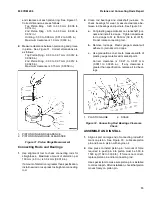
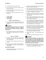
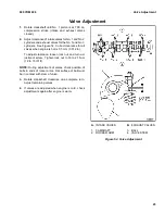
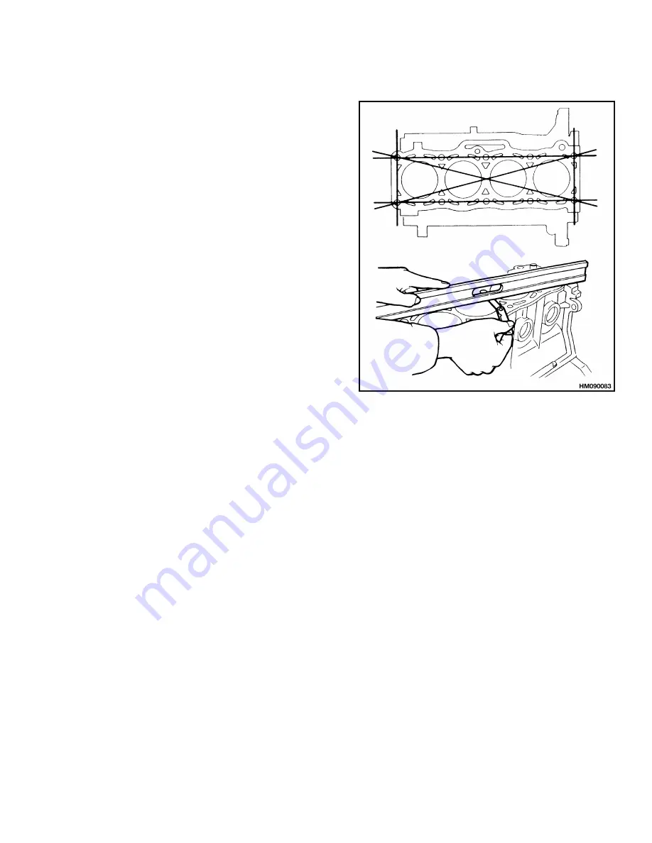
After cylinder block is cleaned, check its surface for
distortion. See Figure 36.
If amount of distortion is greater than 0.15 mm
(0.0059 in.), grind surface of cylinder block. Max-
imum amount of correction permitted is 0.20 mm
(0.008 in.).
2.
Check cylinder bores for wear and damage. Mea-
sure each bore.
Correct dimension is 86.00 to
86.019 mm (3.3858 to 3.3866 in.).
Wear limit
above this dimension is 0.015 mm (0.001 in.).
Repair cylinder block or use bigger pistons as nec-
essary.
Figure 36. Cylinder Block Insepction
Oil Pump Repair
Before removing oil pump, replace sending unit with
pressure gauge and check oil pressure. Minimum oil
pressure at governed rpm is approximately 275 kPa
(40 psi). If pressure is less than specification, oil pump
or engine bearings need repair.
REMOVE
1.
Remove bracket for cooling fan.
2.
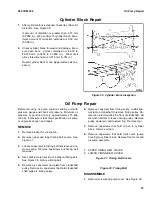
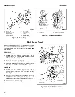
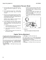
Remove upper and lower timing belt covers. See
Figure 37.
3.
Loosen capscrews for timing belt tensioner and re-
move spring. Remove capscrews and timing belt
tensioner.
4.
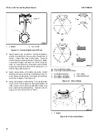
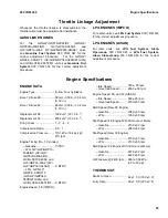
Use chalk to mark direction of rotation of timing belt.
See Figure 38. Remove timing belt.
5.
Remove six capscrews and plate from crankshaft
pulley. Remove six capscrews that hold crankshaft
shaft pulley to timing pulley.
6.
Remove capscrew from timing pulley. Install spe-
cial tool on crankshaft to remove timing pulley. Ro-
tate tool until it touches the front of crankshaft. Hit
tool with hammer to loosen timing pulley. Remove
pulley, dowel pin, and tapered ring. Remove tool.
7.
Remove capscrews that hold oil pan to cylinder
block. Remove oil pan.
8.
Remove capscrews that hold front cover (pump
housing) to cylinder block. Remove front cover and
oil pump assembly.
1.
UPPER TIMING BELT COVER
2.
LOWER TIMING BELT COVER
Figure 37. Timing Belt Covers
Figure 38. Timing Belt
DISASSEMBLE
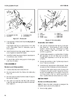
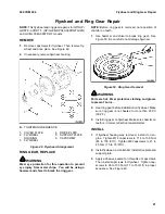
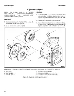
1.
Remove screws and pump cover. See Figure 39.
15
Summary of Contents for GDP16-20AF
Page 37: ......


