Oil Pump Repair
600 YRM 496
1.
SCREW
2.
COVER
3.
OUTER GEAR
4.
INNER GEAR
5.
FRONT COVER
(HOUSING)
6.
OIL SEAL
7.
PLUNGER
8.
SNAP RING
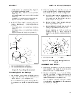
Figure 39. Oil Pump
2.
Remove outer gear and inner gear from pump body.
3.
Remove snap ring and plunger assembly from
housing.
CLEAN
WARNING
Cleaning solvents can be flammable and toxic and
can cause skin irritation.
When using cleaning
solvents, always follow the solvent manufacturer’s
recommended safety procedures.
Clean all parts in solvent. Make sure all machined sur-
faces are smooth.
INSPECT
1.
Check front cover (pump housing) and pump cover
for wear or damage. Check plunger spring for dam-
age.
2.
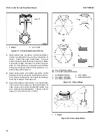
Measure parts of oil pump. See Figure 40.
a.
Measure clearance between gears and cres-
cent. Correct clearance is 0.20 to 0.32 mm
(0.008 to 0.013 in.). If clearance is more than
0.35 mm (0.014 in.), repair as necessary.
b. Measure clearance between crescent and
teeth of inner gear. Correct clearance is 0.267
to 0.380 mm (0.0105 to 0.0150 in.). If clear-
ance is more than 0.40 mm (0.0157 in.), repair
as necessary.
c.
Use straight edge to measure side clearance
of gears. Correct clearance is 0.03 to 0.63 mm
(0.0012 to 0.0248 in.). If clearance is more than
0.10 mm (0.004 in.), repair as necessary.
d. Measure clearance between body and outer
gear. Correct clearance is 0.090 to 0.184 mm
(0.0035 to 0.0072 in.). If clearance is more than
0.20 mm (0.008 in.), repair as necessary.
ASSEMBLE
1.
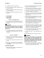
Install oil seal in oil pump housing. Make sure front
edge of oil seal is even with outer edge of housing.
See Figure 39.
2.
Lubricate gears with engine oil. Then install gears
in housing.
3.
Install pump cover. Apply thread-locking compound
on screws for pump cover. Then install screws.
4.
Install plunger assembly and snap ring.
16
Summary of Contents for GDP16-20AF
Page 37: ......


