Engine Specifications
600 YRM 496
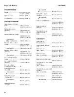
CYLINDER HEAD
Height .................................. 91.25 to 92.05 mm
(3.620 to 3.624 in.)
Distortion Limit..................... 0.15 mm (0.006 in.)
Grinding Limit ...................... 0.20 mm (0.008 in.)
VALVE MECHANISM
Inside Diameter of Valve
Guide ................................... 8.07 to 8.09 mm
(0.3177 to 0.3185 in.)
Clearance in Guide
(Exhaust) ............................. 0.025 to 0.060 mm
(0.001 to 0.0024 in.)
Clearance in Guide (Intake)..
0.025 to 0.060 mm
(0.001 to 0.0024 in.)
– Service Limit
(Intake and Exhaust) ....... 0.20 mm (0.008 in.)
Diameter of Valve Stem
(Intake) ................................ 8.03 to 8.045 mm
(0.3161 to 0.3167 in.)
– Service Limit ................ 7.980 mm (0.3142 in.)
Diameter of Valve Stem
(Exhaust) ............................. 8.025 to 8.045 mm
(0.3159 to 0.3167 in.)
– Service Limit ................ 7.975 mm (0.3140 in.)
Valve Head Thickness
(Intake) ................................ 0.5 mm (0.020 in.)
Valve Head Thickness
(Exhaust) ............................. 1.0 mm (0.040 in.)
Valve Face Angle
(Intake and Exhaust) ........... 30
Spring Free Length
- Outer FE............................ 52.4 mm (2.063 in.)
– Service Limit
FE.................................... 50.8 mm (2.00 in.)
Spring Free Length
- Outer F2......................... 52.2 mm (2.055 in.)
– Service Limit
F2 .................................... 50.6 mm (1.992 in.)
Spring Free Length
- Inner FE............................. 45.7 mm (1.799 in.)
– Service Limit
FE.................................... 44.3 mm (1.744 in.)
Spring Free Length
- Inner F2 ............................. 47.7 mm (1.878 in.)
– Service Limit
F2 .................................... 46.3 mm (1.823 in.)
Rocker Arm Shaft Diameter..
15.966 to 15.984 mm
(0.6286 to 0.6293 in.)
Rocker Arm Bore
Diameter .............................. 16.000 to 16.027 mm
(0.6299 to 0.6311 in.)
Clearance Between
Rocker Arm and
Shaft .................................... 0.016 to 0.061 mm
(0.0006 to 0.0024 in.)
CAMSHAFT
Cam Lobes to
Production Limit................... 37.102 mm (1.4607 in.)
Cam Lobes to Service
Limit ..................................... 36.902 mm (1.4528 in.)
Bearing Journals
(Nos. 1 and 5) ..................... 31.940 to 31.965 mm
(1.2575 to 1.2585 in.)
Bearing Journals
(Nos. 2, 3, and 4) ................ 31.910 to 31.935 mm
(1.2563 to 1.2573 in.)
Bearing Journal Wear Limit..
0.05 mm (0.002 in.)
Clearance Between Journals
and Bore
(Nos. 1 and 5) ..................... 0.035 to 0.085 mm
(0.0014 to 0.0033 in.)
Clearance Between Journals
and Bore
(Nos. 2, 3, and 4) ................ 0.065 to 0.115 mm
(0.0026 to 0.0045 in.)
End Clearance..................... 0.08 to 0.16 mm
(0.003 to 0.006 in.)
– Service Limit ................ 0.20 mm (0.008 in.)
26
Summary of Contents for GDP16-20AF
Page 37: ......


