c.
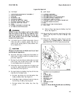
Install battery lockdown bar on top of battery
and engage with bar on side of battery tray.
See Figure 31.
d.
Install lockwasher and flange nut on battery
lockdown bar. Tighten flange nut to 2.0 to
2.5 N•m (18 to 22 lbf in). Install cap on battery
lockdown bar. See Figure 31.
13.
Install power distribution module (PDM) and three
flange bolts on battery tray. Tighten flange bolts to
3.2 to 3.5 N•m (28 to 31 lbf in). Connect the PDM
to chassis wire harness. Install ground strap on
frame. See Figure 31.
14.
Install rear side covers and hood and seat combi-
nation. See section Hood, Seat, and Side Covers
Replacement for procedures.
15.
Install overhead guard. See section Overhead
Guard Replacement for procedures.
16.
Check all fluid levels and fill as needed. See
Peri-
odic Maintenance
8000YRM1774 for quantities
and procedures.
CAUTION
Disposal of lubricants and fluids must meet local
environmental regulations.
17.
Empty drain pan contents.
Transmission Replacement
REMOVE
WARNING
The lift truck must be put on blocks for some
types of maintenance and repairs. The removal of
the following assemblies will cause large changes
in the center of gravity: mast, drive axle, engine,
transmission, and counterweight. When the lift
truck is put on blocks put additional blocks in the
following positions to maintain stability:
•
Before removing the mast and drive axle,
put blocks under the counterweight so the
lift truck cannot fall backward.
•
Before removing the counterweight, put
blocks under the mast assembly so the lift
truck cannot fall forward.
The surface must be solid, even, and level when
the lift truck is put on blocks. Make sure that any
blocks used to support the lift truck are solid, one
piece units. See the Operating Manual or Periodic
Maintenance 8000YRM1774.
WARNING
The transmission is heavy. Make sure that any lift-
ing device has enough capacity to lift the weight.
The transmission can weigh approximately
83.8 kg (184.7 lb).
NOTE:
Make sure the transmission is supported by
blocks or a lifting device before removing the engine.
1.
Remove engine from lift truck. See section Re-
move, Engine Replacement for procedures.
2.
Remove seal plate for brake and throttle pedals.
See Figure 6.
CAUTION
Disposal of lubricants and fluids must meet local
environmental regulations.
3.
Place a suitable container under transmission.
Disconnect transmission cooling lines.
4.
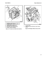
Remove drain fitting from transmission housing
and drain transmission oil. See Figure 36.
5.
Disconnect and cap suction hose from hydraulic
gear pump inlet port. Cap hydraulic gear pump in-
let port. See Figure 36.
6.
Disconnect and cap hydraulic hose from hydraulic
gear pump outlet port. Cap hydraulic gear pump
outlet port. See Figure 36.
7.
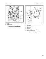
Connect a lifting device to the eyebolt bracket.
See Figure 26.
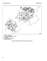
8.
Remove capscrew, washer, snubbing washers,
and isolators from the mount bracket at the rear of
the transmission. See Figure 37.
9.
Use the lifting device to carefully lift the transmis-
sion from the frame.
Engine Replacement
0100 YRM 1766
38


