NOTE:
Perform Step 5 for lift trucks equipped with
gas or LPG engines.
5.
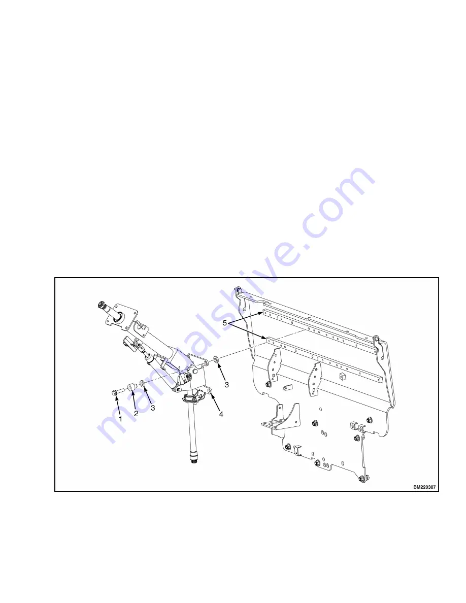
Remove four capscrews, four bushings and steer-
ing column from cowl standoffs. See Figure 11.
NOTE:
Perform Step 6 for lift trucks equipped with
diesel engines.
6.
Remove four capscrews, four bushings, four iso-
lators, steering column and four isolators from
cowl standoffs. See Figure 11.
Disassemble
1.
Remove two pins and gas spring from housing.
See Figure 12, for lift trucks manufactured before
January, 2012.
See Figure 13, for lift trucks manufactured after
January, 2012.
2.
Remove two pivot bolts, two bushings, two nuts
and bracket from housing.
See Figure 12, for lift trucks manufactured before
January, 2012.
See Figure 13, for lift trucks manufactured after
January, 2012.
3.
Remove split pin and lower shaft from upper
shaft.
See Figure 12, for lift trucks manufactured before
January, 2012.
See Figure 13, for lift trucks manufactured after
January, 2012.
4.
Remove connector from connector bracket. Re-
move connector bracket, fastener, four screws
and two horn contacts from housing.
See Figure 12, for lift trucks manufactured before
January, 2012.
See Figure 13, for lift trucks manufactured after
January, 2012.
1. CAPSCREW
2. BUSHING
3. ISOLATOR
4. STEERING COLUMN
5. COWL STANDOFF
Figure 11. Steering Column Remove/Install
0100 YRM 1243
Steering Column
13
Summary of Contents for GP80VX
Page 13: ...Figure 7 Gas Spring Installation 0100 YRM 1243 Hood Seat and Side Covers Replacement 9...
Page 40: ...Figure 27 Cummins QSB 3 3L Diesel Engine and Transmission Engine Replacement 0100 YRM 1243 36...
Page 52: ...Figure 33 Cummins 4 5L Diesel Engine and Transmission Engine Replacement 0100 YRM 1243 48...
Page 57: ...Thank you very much for your reading Please Click Here Then Get More Information...


