WARNING
DO NOT make repairs or adjustments unless you
have been properly trained and authorized to do
so. Improper repairs and adjustments can create
dangerous operating conditions. DO NOT operate
a lift truck that needs repairs. Report the need for
repairs to your supervisor immediately. If repair is
necessary, attach a DO NOT OPERATE tag to the
control handle and disconnect the battery.
Disconnect the battery and discharge the internal
or external capacitors before opening any com-
partment covers or inspecting or repairing the
electrical system. DO NOT place tools on top of
the battery. If a tool causes a short circuit, the high
current flow from the battery can cause personal
injury or property damage.
Some checks and adjustments are performed with
the battery connected. DO NOT connect the bat-
tery until the procedure instructs you to do so.
Never wear jewelry or other metallic items on your
fingers, arms, or neck when working near electri-
cal components. Metal items can accidentally
make an electrical connection and cause injury.
Before performing any tests or adjustments, block
the lift truck to prevent unexpected movement.
The capacitors in the transistor controllers can
hold an electrical charge after the battery is dis-
connected. To prevent an electrical shock and per-
sonal injury, discharge the internal or external ca-
pacitors before inspecting or repairing any compo-
nent in the electrical compartments. Make certain
that the battery has been disconnected.
DO NOT short across the motor controller termi-
nals with a screwdriver or jumper wire.
CAUTION
To avoid controller damage, always disconnect the
battery, discharge the internal or external capaci-
tors, and never put power to the controller while
any power wires are disconnected. Never short
any controller terminal or motor terminal to the
battery. Make sure to use proper procedure when
servicing the controller.
1.
Move the lift truck to a safe, level area and
completely lower the forks. Turn the key switch to
the
OFF
position and attach a
DO NOT
OPERATE
tag to the control handle. Block the
drive wheel to prevent unexpected movement.
2.
Disconnect the battery power cable connector
from the truck connector located on the top-left
side of the frame. Pull the battery cable connector
handle to separate the battery connector from the
truck connector.
3.
Remove the operator compartment cover.
4.
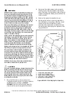
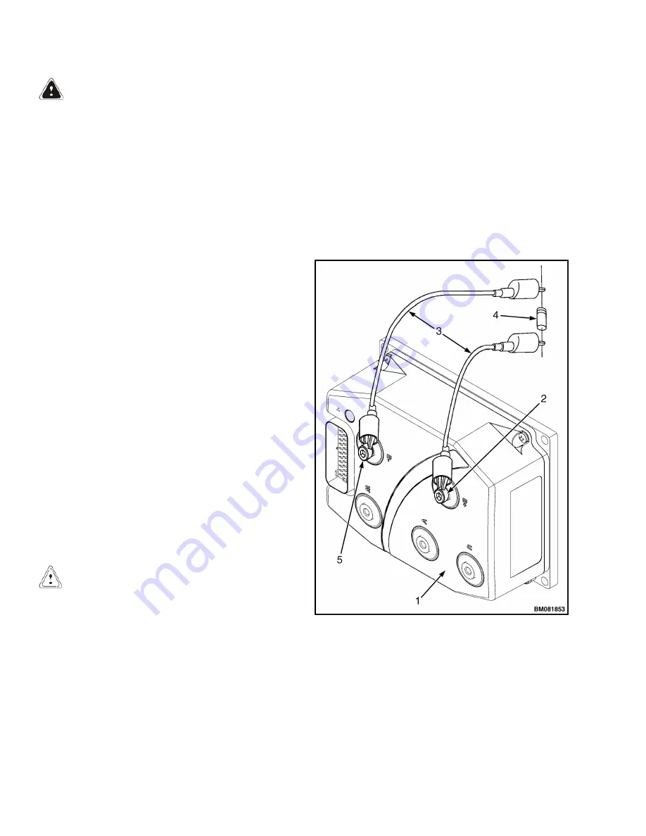
Discharge the internal or external capacitors in
the controllers by connecting a 200-ohm, 2-watt
resistor across the controller B(+) and B(-)
terminals of the combination controller. Remove
the resistor after discharging the capacitors. See
Figure 9030-03-1.
1. TRACTION CONTROLLER
2. POSITIVE CONNECTION
3. INSULATED JUMPER WIRES
4. 200-OHM, 2-WATT RESISTOR
5. NEGATIVE CONNECTION
Figure 9030-03-1. Discharging the Capacitors
General Maintenance and Diagnostic Data
ELECTRICAL SYSTEM
Check the Service Manual section in Yale Axcess Online for possible updates and check pertinent Bulletins
9030-03-2
Confidential/Proprietary - Do Not Copy or Duplicate
Summary of Contents for MPB045VG
Page 1: ...Maintenance CONTROLLER DIAGNOSTICS MPB045VG A245 PART NO 550095689 9000 YRM 1671 ...
Page 4: ......
Page 6: ......
Page 10: ...9030 4 ...
Page 24: ...NOTES 9030 03 14 ...
Page 83: ......
Page 84: ...9000 YRM 1671 10 19 9 15 1 15 12 14 10 14 4 14 ...


