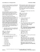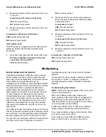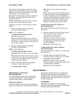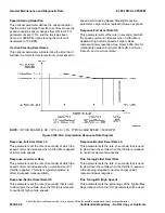
connections or poor ground acts as an additional load
in the circuit, causing low voltage pushing current, or
amperage, through a device.
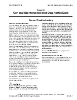
A voltmeter is used to perform:
•
Measurement of force
•
Presence of voltage
•
Voltage drops
When using a voltmeter to determine if voltage is
present and capable of operating a device, connect
the positive meter lead to the power circuit of a
device’s connector and connect the negative meter
lead to the negative battery terminal.
Measuring the voltage drop is performed by
connecting the positive test lead to the positive side of
the device while simultaneously connecting the
negative meter lead to the negative side of the device.
The test can also be performed across a section of
wire that is faulty and suspected of having excessive
resistance. A voltage drop must be performed while
the device is operating. In a circuit with a single load
device, the device will drop the total voltage of the
circuit. If the device drops less than battery voltage, it
can be assumed that the circuits are using the
remaining voltage as a source of excessive resistance
or a poor connection exists, assuming the battery
state-of-charge is correct.
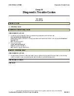
1.
Verify battery connectors for loose terminals and
appropriate crimping. Measure voltage between
terminal before FU1 and B(-).
NOTE:
Key in ON position.
Is voltage 24 ± 2.5 Vdc?
YES-
NO-
Disconnect battery and proceed to Step 2.
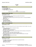
2.
Measure resistance between truck frame and
each of the following test points:
•
Battery postivie wire after FU1
•
B(+) and B(-)
•
U-Phase cable
•
V-Phase cable
•
W-Phase cable
•
Pump positive cable
•
Pump negative cable
Is resistance ≥1M ohm?
YES-
Charge battery, perform battery maintenance, for
non-maintenance free batteries, read battery Specific
Gravity level to be within manufacturer specification.
NO-
Inspect for all cable insualtion throughout the
truck. Inspect battery corrosion around terminals for
proper crimping.
3.
Measure battery voltage between terminal after
FU1 and B(-).
NOTE:
Key in ON position.
Is voltage 24 ± 2.5 Vdc?
YES-
NO-
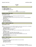
4.
Measure continuity of Fuse FU1.
Is resistance <1 ohm?
YES-
NO-
Replace Fuse FU1.
5.
Ensure battery disconnect switch in UP position,
measure voltage between TS04 and B(-).
Is voltage same as battery voltage?
YES-
NO-
Verify TS04 and TS05 terminal connections.
Refer to
ELECTRICAL SYSTEM 2200YRM1508
for battery disconnect switch checks.
6.
Measure continuity of Fuse FU2.
Is resistance <1 ohm?
YES-
NO-
Replace Fuse FU2.
7.
Measure resistance between key switch terminals
TS04 and TS05.
Is resistance <1 ohm?
YES-
Inspect CPS 01 socket 1 for appropriate
crimping in terminals. Inspect voltage between
CPS01 socket 1 and B(-) to be same as battery
voltage. If not, inspect circuit 010 for excessive
resistance, damage, loose, or open connections.
NO-
Inspect key switch terminals to be
appropriately connected. If connections are clean
and secure and resistance is ≥1 ohm, replace key
switch.
General Maintenance and Diagnostic Data
ELECTRICAL SYSTEM
Check the Service Manual section in Yale Axcess Online for possible updates and check pertinent Bulletins
9030-03-4
Confidential/Proprietary - Do Not Copy or Duplicate
Summary of Contents for MPB045VG
Page 1: ...Maintenance CONTROLLER DIAGNOSTICS MPB045VG A245 PART NO 550095689 9000 YRM 1671 ...
Page 4: ......
Page 6: ......
Page 10: ...9030 4 ...
Page 24: ...NOTES 9030 03 14 ...
Page 83: ......
Page 84: ...9000 YRM 1671 10 19 9 15 1 15 12 14 10 14 4 14 ...


