3.
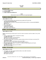
Measure resistance of tiller card switch JP12, pin
1 and pin 3.
Is resistance 2.7K ohms ± 0.27K ohms
YES-
NO-
Replace faulty switch.
4.
Measure resistance of tiller card switch JP15, pin
1 and pin 2.
Is resistance 1.4K ohms ± 0.14K ohms
YES-
Suspect faulty tiller card.
NO-
Replace faulty switch.
Lift Function Fault
If the lift function is inoperative and no code has been
displayed, perform the following troubleshooting
procedures:
1.
Open tiller head assembly and inspect tiller card.
Are lower switches connected to tiller card
connectors JP10 and JP14?
YES-
NO-
Connect switches.
2.
Disconnect JP10 and connect meter probes at
switch connector sockets (blue and black leads)
and operate switch.
Is resistance <1 ohm?
YES-
NO-
Replace faulty switch.
3.
Measure resistance of tiller card switch JP10, pin
1 and pin 3.
Is resistance 2.7K ohms ± 0.27K ohms
YES-
NO-
Replace faulty switch.
4.
Measure resistance of tiller card switch JP14, pin
1 and pin 2.
Is resistance 1.4K ohms ± 0.14K ohms
YES-
Suspect faulty tiller card.
NO-
Replace faulty switch.
Multiplexing
MULTIPLEXING AND THE CANBUS
Controller Area Network (CAN) Bus communication
allows multiple modules to communicate with each
other using the same digital data on a shared network,
this method of communication is known as
multiplexing. The CANbus is a pair of twisted insulated
wires that interconnect all the modules on the network.
The data transmitted is a digital encoded format.
Digital means only two states are used to transmit
data, High/On and Low/Off. This eliminates the need
for each module to be hard wired to each sensor.
Using Multiplexing, sensor information that may be
received by one module, can then be shared with all
other modules. The information is sent out over the
CANbus in an encoded form and any other module
that requires the information can pick it out from the
data stream.
The CANbus has two termination resistors (120 ohms)
that are connected in parallel. When resistance checks
are performed, a normal operating system will display
60 ohms between the CAN LO and CAN HI circuits.
The first 120 ohm termination resistor is located inside
the Tiller Control Card. To diagnose, proceed to
Troubleshooting the Tiller Control Card Termination
Resistor.
The second 120 ohm termination resistor is located in
the Traction Controller. To diagnose, proceed to
Troubleshooting the Traction Controller Termination
Resistor.
Troubleshooting the CANbus
NOTE:
Refer to the latest Diagram YRM for the most
current circuit information.
When the CANbus is active and modules are
communicating, CAN HI and CAN LO voltage will be
approximately 5 volts when added together. If both
CAN HI and CAN LO have consistent 2.5 volt, there is
no communication on the CANbus.
If CAN HI is shorted to B(-) or CAN LO is shorted to
battery voltage, network communication will stop.
If you measure battery voltage on the data link, there
is a short to power in the circuit.
If you measure 0 volts while the CANBus is active,
there is a short to B(-) or an open in the circuit.
General Maintenance and Diagnostic Data
ELECTRICAL SYSTEM
Check the Service Manual section in Yale Axcess Online for possible updates and check pertinent Bulletins
9030-03-6
Confidential/Proprietary - Do Not Copy or Duplicate
Summary of Contents for MPB045VG
Page 1: ...Maintenance CONTROLLER DIAGNOSTICS MPB045VG A245 PART NO 550095689 9000 YRM 1671 ...
Page 4: ......
Page 6: ......
Page 10: ...9030 4 ...
Page 24: ...NOTES 9030 03 14 ...
Page 83: ......
Page 84: ...9000 YRM 1671 10 19 9 15 1 15 12 14 10 14 4 14 ...

