DTC 30037
AlrmCoil
POSSIBLE CAUSE
A. ALARM WIRING FAULT
B. ALARM FAULT
C. FAULTY TRACTION CONTROLLER
NOTE
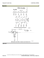
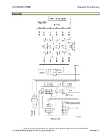
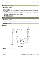
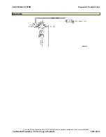
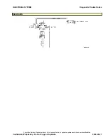
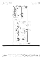
Please refer to the end of this procedure for supporting diagrams.
COMPONENT OPERATIONAL CHECK
PROCEDURE OR ACTION:
1. Conduct a visual inspection of all connectors/wiring associated with the fault code.
Are any faults detected/observed?
YES:
Repair/replace connector or wiring associated with faults found. Refer to the appropriate
Electrical
System
YRM .
NO:
Proceed to Step 2.
2. Re-key the vehicle.
Is the code still present?
YES:
Proceed to CAUSE A.
NO:
Problem may be intermittent.
CAUSE A - ALARM WIRING FAULT
PROCEDURE OR ACTION:
NOTE:
Perform Step 1 with key in ON position.
1. Disconnect alarm connector TS09 and measure voltage between socket 1 and B(-).
Is voltage 24 ± 2.5 Vdc?
YES:
Disconnect battery and proceed to Step 2.
NO:
Inspect circuit 239 for open or short.
2. Disconnect the traction connector CPS01. Measure resistance between the traction connector CPS01, socket
20 and the alarm connector TS09.
Is resistance <1 ohm?
YES:
Connect traction controller connector CPS01 and proceed to CAUSE B.
NO:
Inspect ground control circuit 045 for open or short.
CAUSE B - ALARM FAULT
PROCEDURE OR ACTION:
NOTE:
Key in ON position.
NOTE:
Operate alarm.
1. Measure continuity between the alarm connector TS09 and B(-).
Is continuity present?
YES:
Replace faulty alarm.
NO:
Proceed to CAUSE C.
ELECTRICAL SYSTEM
Diagnostic Trouble Codes
Check the Service Manual section in Yale Axcess Online for possible updates and check pertinent Bulletins
Confidential/Proprietary - Do Not Copy or Duplicate
9030-20-13
Summary of Contents for MPB045VG
Page 1: ...Maintenance CONTROLLER DIAGNOSTICS MPB045VG A245 PART NO 550095689 9000 YRM 1671 ...
Page 4: ......
Page 6: ......
Page 10: ...9030 4 ...
Page 24: ...NOTES 9030 03 14 ...
Page 83: ......
Page 84: ...9000 YRM 1671 10 19 9 15 1 15 12 14 10 14 4 14 ...


