load; the height to which the load is raised; the amount of
forward or backward tilt; and the dynamic forces created
when the truck is moving.
These dynamic forces are caused by things like accelera-
tion, braking, turning, and operating on uneven surfaces or
on an incline. These factors must be considered when trav-
eling with an unloaded truck, as well, because an unloaded
truck will tip over to the side easier than a loaded truck with
its load in the lowered position.
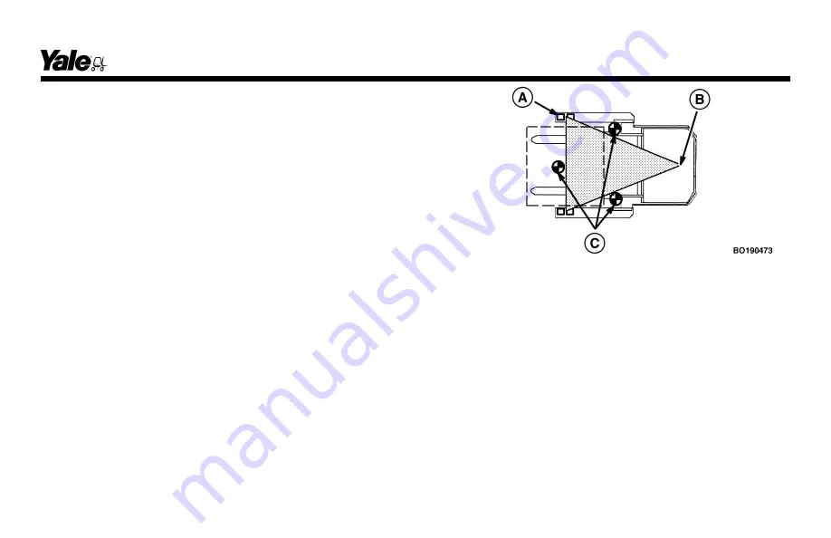
In order for the lift truck to be stable (not tip over forward or
to the side), the CG must stay within the area of the lift
truck represented by a triangle drawn between the load
wheels and the pivot of the steering axle.
A.
LOAD WHEEL AXLE
B.
STEERING AXLE PIVOT
C.
CG - TRUCK WILL TIP OVER
If the CG moves forward of the load wheels, the lift truck
will tip forward. If the CG moves outside of the line repre-
sented by the triangle drawn between the load wheels and
the steering axle pivot, the lift truck will tip to that side.
Stability and traction will also be affected if the drive unit
articulation stops are not adjusted properly. The articulation
stop screws must be adjusted to the proper setting as listed
on the nameplate and in the Articulation Chart found in the
Maintenance
section.
Operating Procedures
37
Summary of Contents for MSW020-E
Page 12: ...Figure 2 Nameplate Warning Labels and Decals Model Description 10...
Page 60: ...Figure 15 Maintenance Points MSW025 030 F Maintenance Schedule 58...
Page 81: ...Figure 23 Remove Install Battery From Battery Power Pack Maintenance 79...
Page 92: ...A TOP VIEW B LEFT VIEW 1 DRIVE END 2 FORK END 3 STRAP Figure 24 Lifting Points Maintenance 90...
Page 93: ...Figure 25 Putting the Lift Truck on Blocks MSW MRW Shown Maintenance 91...
Page 96: ...A TOP VIEW B LEFT VIEW 1 STRAP 2 ANCHOR POINT Figure 26 Lift Truck Tie Downs Maintenance 94...
Page 97: ...Spacer 7 18 5 18 11 17 8 16 1 16 7 14 2 13 9 09 9 08 3 08...


