background image

7

P/N YRD420-KD-F Rev A

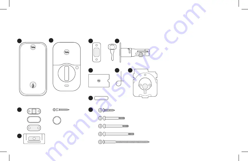
In the Box

Lock

Hardware

b.

c.

d.

e.

X 4

X 4

X 2

X 2

X 2

X 2

X 2

Add-Ons


1

2

3

5

7

6

4

UP

1. 

Exterior Keypad

2. 

Interior Lock

3. 

Strike Plate

4. 

Adjustable Deadbolt & Key

5. 

Manual

6. 

Reset Pin

7. 

Mounting Plate

8. 

AA Batteries

9. 

Screws

a. 

Strike Plate and Deadbolt Screws

b. 

Teal Screw Set B

c. 

Black Screw Set C

d. 

Silver Screw Set D

e. 

Optional Security Strike Plate Screws

10. 

DoorSense 

a. 

Housing

b. 

Cover

c. 

Mounting Tape

d. 

Screws

e. 

Flush Mount Cap

11. 

Smart Module 

(Included with select models)

8

10

9

11

a.

a.

d.

e.

b.

c.

AA

Summary of Contents for real living Z-Wave Plus YRD420-F-ZW3

Page 1: ...rk primary controller is missing or otherwise inoperable Adding a Yale Z Wave Plus v2 Smart Module to your Assure Lock Z Wave System If prompted scan QR code 1 Open Z Wave system s smart home or alarm...

Page 2: ...ence in a residential installation This equipment generates uses and can radiate radio frequency energy and if not installed and used in accordance with the instructions may cause harmful interference...

Page 3: ...e Access App Install Your Lock Follow the step by step Installation Guide in this manual pages 8 22 or refer to the app for installation instructions with helpful videos Note If you use the app please...

Page 4: ...P N YRD420 KD F Rev A...

Page 5: ...ver longest screws E 2 3 8 backset use out of box latch setting F 2 3 4 backset adjust latch setting Step 2 point 1 of this manual Greater than A B C or D Equals E or F Less than A Less than B or grea...

Page 6: ...et I 1 edge bore diameter 1 strike pocket diameter and depth Equals I Greater than I Greater than H Adjust diameter to G or H Adjust diameter to I Your door is not a match Your door is not a match Edg...

Page 7: ...te for 2 1 8 54mm Face Bore Center of 1 25mm Edge Bore Center of 1 25mm Edge Bore Centerline Center of 2 1 8 54mm Face Bore Center of 2 1 8 54mm Face Bore I H 1 3 8 35mm Door Thickness B 2 3 8 60mm Ba...

Page 8: ...Center of 1 25mm Edge Bore Center of 1 25mm Edge Bore Centerline Center of 1 1 2 38mm Face Bore Center of 1 1 2 38mm Face Bore 1 1 2 I G 1 3 8 35mm Door Thickness B 2 3 8 60mm Backset E 1 3 4 44 5mm...

Page 9: ...djustable Deadbolt Key 5 Manual 6 Reset Pin 7 Mounting Plate 8 AA Batteries 9 Screws a Strike Plate and Deadbolt Screws b Teal Screw Set B c Black Screw Set C d Silver Screw Set D e Optional Security...

Page 10: ...uct voiding the factory warranty and could lead to failure of the product to provide access 1 Phillips Head Screwdriver 2 Door Checker tear off pages 3 4 of this manual 3 Tape Measure 4 Drill 5 Markin...

Page 11: ...Door Keep your old deadbolt until your new lock has been successfully installed 1a Remove Existing Deadbolt If you have a new door please proceed to step 1b If you have a deadbolt on your door use the...

Page 12: ...g Template Tear off the Door Checker pages 3 4 and follow the guidelines on both sides to measure each aspect of your door and frame There are some cases when existing holes cannot be adjusted to be c...

Page 13: ...shown 3 Check the door thickness It should match either the shape with solid outlines 1 3 4 or the one with dashed outlines 1 3 8 3a Use solid lines as a template for 1 3 4 door thickness 3b Use dashe...

Page 14: ...trike plate screws 3 Make sure UP arrow on the deadbolt is facing upwards 4 Deadbolt latch must be in an unlocked position Note If the deadbolt latch is extended use a small flathead screwdriver to ro...

Page 15: ...s less than 2 1 8 H remove adapter by twisting it off the body of the lock 2 Make sure your deadbolt latch is in an unlocked position Refer to step 2 point 4 page 12 for guidance on how to retract it...

Page 16: ...ece through the designated slot in the mounting plate 5 Tighten screws with a screwdriver to secure the mounting plate As you tighten the screws make sure the mounting plate and the keypad are straigh...

Page 17: ...by pulling it upwards off the body of the interior lock 2 Make sure the side of the cable end with the ridges and the marked line faces outward 3 Push cable into the designated slot until you hear a c...

Page 18: ...the tailpiece through the designated slot on the back of the thumbturn 3 Press the lock against the mounting plate adjusting its position until it clicks into place and the bottom of the lock is held...

Page 19: ...rom the inside Ensure that the deadbolt latch is centered in the face bore hole Ensure that the tailpiece is positioned horizontally and inserted through deadbolt latch slot step 3 point 3 into the th...

Page 20: ...l does not include a Smart Module please proceed to step 9a Insert Yale Smart Module into the designated slot at the top of the body of the lock Note If you purchased your module separately check comp...

Page 21: ...des a cleaner look with more robust performance but requires drilling For surface mount instructions please proceed to step 9b For flush mount instructions please proceed to step 9c 9a Install DoorSen...

Page 22: ...imal performance DoorSense should be mounted within 1 1 2 from the edge of your door frame 5 Ensure DoorSense is in proper position by center aligning it with the Yale logo and adhere it to the door f...

Page 23: ...nting location DoorSense should be mounted 1 1 2 at most from the top edge of the strike plate 6 Mark a hole that s horizontally centered on the door frame and is 5 8 in diameter 7 Drill a 1 2 deep ho...

Page 24: ...eypad will light up in a clockwise pattern Once this happens the lock is in pairing mode Open Yale Access App tap on Set Up a Device and follow the in app setup instructions Make sure you have Yale Ac...

Page 25: ...erprint With entry code Press Enter entry code Press Interior Lock 1 Exterior LED Indicator 2 Wake One Touch Locking Fingerprint Scanner 3 Warnings Menu 4 Submit Entry Code 5 Thumbturn 6 Passage Butto...

Page 26: ...es Pairing success Any key then gear flash red Jammed lock Gear flashes white Pairing Gear flashes red during pairing Pairing failure Interior Lock Alerts LED indicator flashes blue Low battery levels...

Page 27: ...App you should reset it using the app Go to your lock s settings and choose Factory Reset 1 Remove one battery 2 Insert reset pin into the designated reset hole 3 Press and hold the reset pin 4 While...

Page 28: ...long as 30 minutes When using the Auto Lock feature with DoorSense your door will not lock until it is closed Auto Lock can be set up in the lock settings of the app Auto Unlock Auto Unlock knows when...

Page 29: ...the app Automation Auto Lock Door will automatically lock either when door is closed with DoorSense or on a timer Auto Unlock Door will automatically unlock when you arrive home DoorSense Allows you...

Page 30: ...iming Default 60 sec The lock will shut down for the set period of time and not allow operation after the wrong code entry limit has been reached Wrong Code Limit Default 5 times After the set number...

Page 31: ...ock is on for a while then shows no reaction Lights dim Batteries do not have enough power Replace batteries Lock chimes indicating code acceptance but door will not open Check for any foreign objects...

Page 32: ...rify entered code is a valid previously programmed 4 to 8 digit code Vacation mode might be on Only an admin user can switch vacation mode to normal in the app Upon entering an entry code and pressing...

Page 33: ...dleset strike plate Latch engagement into the strike is the main component used for door alignment To adjust knob lever handleset strike plate 1 Remove plate from door frame with a hand screwdriver No...

Page 34: ...iate radio frequency energy and if not installed and used in accordance with the instructions may cause harmful interference to radio communications However there is no guarantee that interference wil...

Page 35: ...1 Yale Locks Z Wave Plus v2 System Integrators Guide Yale Assure Electronic Connected Biometric Deadbolts Document Revision 1 0 June 2023...

Page 36: ...Specific Version 2 8 Command Class Security Version 1 8 Command Class Security 2 Version 1 8 Command Class Device Reset Locally Version 1 9 Command Class Power Level Version 1 9 Command Class Version...

Page 37: ...25 Command Class Application Status Version 1 28 Command Class Transport Service Version 2 28 Command Class Supervision Version 1 28 Command Class Indicator Version 3 28 Command Class Basic Version 2...

Page 38: ...4 Revision History Rev Details 1 0 Initial Release...

Page 39: ...ired and the SmartStart product will be added automatically within 10 minutes of being switched on in the network vicinity Open the Z Wave system s smart home app via smartphone or tablet and follow t...

Page 40: ...user code database and configuration settings will be retained as opposed to set back to defaults Factory Reset Factory resetting the lock with the Z Wave module installed will clear the Z Wave networ...

Page 41: ...the Z Wave specifications As a secure device most of the command classes supported by the lock are required to be sent securely with Z Wave security During enrollment the controller can use the Secur...

Page 42: ...ton Biometric Deadbolt 0x49D2 for YRD420 F ZW3 2nd Generation Assure Keyed Touch Screen Biometric Deadbolt 0x49D3 for YRD430 F ZW3 2nd Generation Assure Keyless Push Button Biometric Deadbolt 0x49D5 f...

Page 43: ...ing the configuration parameter to perform a remote reset However if the DUT is unenrolled excluded from the network through the device menu mode then the user code database and configuration settings...

Page 44: ...target the hex data in the firmware version report must be converted to decimal prior to combining major and minor version into the full version After a controller sends a Version Get command the log...

Page 45: ...Version 4 This command class requires security Yale Z Wave Plus locks support three door lock modes Door Secured 0xFF Door Unsecured 0x00 and Door Unsecured with timeout 0x01 When Auto Relock is enab...

Page 46: ...ort Extended User Code Report Extended User Code Report The master code can be accessed read write using slot 251 0xFB if using version 1 of this command class For version 2 the Master Code Set Get Re...

Page 47: ...tus User Code CC v1 Set User Code CC v1 Report Value Description Value Value Available 0x00 0x00 Enabled Grant Access 0x01 0x01 Disabled 0x02 0x03 0x03 Messaging The user code is accepted but the lock...

Page 48: ...the user Instead it generates an alarm to the Lifeline and does NOT take preventative actions for further attempts to enter the User ID and or User Code 0x03 0x03 One Time Use This PIN is disabled im...

Page 49: ...e Parameters in the lock anytime the lock loses power Even though the Time CC is not secure the Time Set command must be issued at the same or higher security level as when the device was enrolled for...

Page 50: ...a specific region but this will also be 0 for now since there is only a single build of firmware Table 4 Region Specific Values for Firmware ID 0 Upper Nibble Region Value ANZ 0x1 CN 0x2 EU 0x3 HK 0x...

Page 51: ...3 minutes full image 5 minutes patch differential image Command Class Association Version 2 This command class requires security This command class has been implemented per the Z Wave Specification Co...

Page 52: ...mmand Class Battery o Battery Report Command Class Configuration o Configuration Report Command Class Notification o Notification Report Command Class Door Lock o Door Lock Operation Report o Door Loc...

Page 53: ...sholds Any manual keypad Lock Operation when lock is under the battery thresholds or Power Cycle Lock Door Lock Operation Report Manual or Keypad Unlock Lock Door Lock Configuration Report Door Lock C...

Page 54: ...while locking 0x06 0x0B 0x02 Deadbolt jammed while unlocking 0x06 0x0B Keypad Lock 0x12 0x 01 max users Where Alarm level represents user slot number 0x06 0x05 Keypad Unlock 0x13 0x 01 max users Wher...

Page 55: ...mplete locked 0x06 0x09 User deleted 0x21 0x 01 max users User was deleted Alarm level user slot number 0x06 0X0D single 0x00 All User codes were deleted 0X0C all Non Access 0x26 0x 01 max users A Non...

Page 56: ...ased 0x64 0x 01 max users All Schedule Types were Set erased set for User ID specified in Alarm Level If Alarm Level 0xFF then all users were affected 0x06 0xFE All Schedule Types Enabled Disabled 0x6...

Page 57: ...non access user is out of schedule this alarm will be sent instead of the non access alarm 0x06 0xFE Fingerprint Unlock 0x91 0x 01 Max Fingerprint Slot User credentials unlock credential type 0x02 Al...

Page 58: ...ly repeating scheduled pin codes assigned to user codes This requires additional Hardware and calibration within the Yale Access App The Yale lock also supports a 3rd low battery alarm too low to oper...

Page 59: ...1 byte 0x01 High Volume 0x03 Silent 0x01 High Volume Set Volume Level to high 1 low 2 or silent 3 53 2 Auto Relock 1 byte 0x00 Disable 0xFF Enable 0x00 Disable Set Auto Relock feature to enable or dis...

Page 60: ...r passage mode 76 11 One Touch Locking 1 byte 0x00 Disable 0xFF Enable 0xFF Enable Set One Touch Locking feature to enable or disable 51 13 Lock Status LED 1 byte 0x00 Disable 0xFF Enable 0x00 Disable...

Page 61: ...to Relock Time to values 0x01 or 0x02 it will always report back value of 0x03 When Operation Mode feature is set to Passage Mode this also results in disabling the following configuration parameters...

Page 62: ...Exterior Lock Interior OFF Keypad LED is OFF Inside LED OFF ON Numbers 0 9 Flash Inside LED Flashes In order to set the Indicator ID 0x50 with Property 0x02 set values to 0x00 for off and 0x01 0x63 or...

Page 63: ...or Lock Operation Report Door Lock Mode 0x00 The Basic Get Current Value Basic Get Duration and Basic Get Target Value are mapped to Door Lock Operation Get and Basic Set is directly mapped to Door Lo...

Reviews: