background image

Page 4

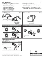
Unit Adjustment

L

A

T

C

H

L

A

T

C

H

O

P

E

N

IN

G

Delayed Action

Closing Cycle

1B

Closing Speed Controls                                            Figure 1.

SWEEP

S

W

E

E

P

CLOSED

CLOSED

Standard Closing Cycle

1A

DELAY

RA

NG

E

10°

10°

70°

Closing Speed Controls                                            Figure 2.

Closing Power Control                                              Figure 3.

Opening Door Control (Figure 4.)

!

!

Backcheck ( B ) valve controls the hydraulic resistance to

door opening. NEVER close this valve completely – it is
not to provide a positive stop.

Backcheck position (”P”) valve controls the door angle

where backcheck cushioning starts. Valve normally closed.

“ ”

Opening Door Control                                             Figure 4.

Opening Cycle

BACKCH

ECK

Backcheck Control                                                  Figure 5.

Closing Speed Controls (Figure 1A or 1B And 2.)

Standard Closer Only

Delayed Action Closer Only

Valve “S/D” Controls Sweep Range.
Valve “L” Controls Latch Range.

Valve “S/D” Controls Delay Range.
Valve “S” Controls Sweep Range.
Valve “L” Controls Latch Range.

1/8”
Hex
Key

Slow

Fast

1/8”
Hex
Key

Increase

Decrease

Standard

S/D (Sweep)

L (Latch)

Delayed Action

S/D (Delayed

Action)

S (Sweep)

L (Latch)

1/8”
Hex
Key

“B”
(NEVER
Close
Completely)

1/8”
Hex
Key

Increase

Decrease

Open for backcheck
later in door-opening
cycle.

Backcheck Position

“P”
Normally
Closed

Backcheck Cushion

Power

Adjustment

Nut

To increase power

11/16"

wrench

To decrease power

11/16"

wrench

Note: Maximum of 15 360°
turns of Power Adjustment
Nut.

Closing Power Adjustment (Figure 3.)

!

Adjust as required.

Sweep &

Latch

Delay

An ASSA ABLOY Group brand

3000 Highway 74 East  •  Monroe, NC 28112
Tel: (800)-438-1951  •  Fax: (800)-338-0965

www.yalecommercial.com

Yale ® is a registered trademark of Yale Security Inc., an ASSA ABLOY Group company.
Copyright © 2002, 2009, Yale Security Inc., an ASSA ABLOY Group company. All rights reserved.
Reproduction in whole or in part without the express written permission of Yale Security Inc. is prohibited.

Summary of Contents for SCP400 Series

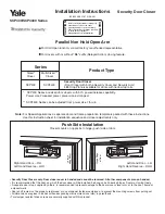
Page 1: ... 6 t Push Side Installation Closer mounts on opposite to hinge push side of door Right Hand Door RH Left Hand Reverse LHR Hinge Edge of Door Left Hand Door LH Right Hand Reverse RHR Security Door Closers only Door closer cover is handed and cannot be reversed All other components are non handed It is recommended that the door on which the door closer will be installed be hung on ball bearing hinge...

Page 2: ...or Size mm inches Full Clockwise Turns of Closer Power Adjustment Nut SCP4400 ONLY Interior Door Exterior Door 28 32 0 7 0 8 33 36 0 85 0 9 37 42 0 95 1 05 42 48 1 1 1 2 Closer is shipped set at median power setting 0 2 5 8 2 5 8 11 Do Not Scale Drawing Left Hand Door Shown Dimensions are in inches mm Maximum Door Swing 180 conditions permitting NOTE Maximum of 15 360 turns of Power Adjustment Nut...

Page 3: ... Place main arm on shaft aligning mark on arm with pinion flat on pinion shaft Z for Left Hand Door Y for Right Hand Door Secure with 1 4 20 x 1 2 13 round head machine screw with lock washer 80 9344 0621 010 06 09 Main Arm Screw with Lock Washer Reopen valves closed in Step 2 Turn Counterclockwise With door closed align soffit plate with mounting holes in frame Fasten soffit plate to frame with f...

Page 4: ... D Controls Delay Range Valve S Controls Sweep Range Valve L Controls Latch Range 1 8 Hex Key Slow Fast 1 8 Hex Key Increase Decrease Standard S D Sweep L Latch Delayed Action S D Delayed Action S Sweep L Latch 1 8 Hex Key B NEVER Close Completely 1 8 Hex Key Increase Decrease Open for backcheck later in door opening cycle Backcheck Position P Normally Closed Backcheck Cushion Power Adjustment Nut...

Reviews: