background image

5

SINGLE & DOUBLE GIRDER TOP-RUNNING BRIDGES

WITH INDIVIDUAL MOTOR DRIVEN

END TRUCKS

P/N: 11532620   REV. AA

   September 2018

OPERATING PRECAUTIONS

WARNING

These bridge cranes are not designed nor intended to be 

used for support or transport of people or for transporting 

loads over people.


Safe operation of an overhead hoist is the operator’s responsibility. 

Listed below are some basic rules that can make an operator aware 

of dangerous practices to avoid and precautions to take for his own 

safety and the safety of others. Observance of these rules in addition 

to frequent examinations and periodic inspection of the equipment 

may save injury to personnel and damage to the equipment.

DO NOT load bridge beyond rated capacity.
DO NOT subject bridge crane to side loads. Always center trolley 

over load when hoisting.
DO NOT stand and DO NOT cause or allow others to stand or get 

under any load the bridge crane is supporting.
DO keep clear, and make sure others keep clear, of any load the 

bridge crane is supporting.
DO NOT attempt to operate bridge crane before completing tests 

and adjustments.
DO NOT run bridge crane into end stops, other bridge cranes, or 

any obstruction on beam. Improper and careless operation can 

result in a hazardous condition for operator and load.
ALWAYS be sure load is clear of obstruction before traversing 

load.

CAUTION

If bridge crane is mounted on an open-end runway rail, then 

end stops must be installed to prevent bridge crane from 

running off the end of the runway rail resulting in injury to 

the operator and others and damages to the load and other 

property. End stops for the trolley must also be installed.

Refer to hoist and trolley instruction manuals for safety warnings 

on hoists and trolleys.
Read and comply with ANSI B30.2 or B30.17-latest edition.
Read and comply with all local, state and national safety codes.

GENERAL

Motor driven cranes are usually operated from a pendant push button 

station or radio control, which controls the bridge electrically. The 

push button may be suspended from the bridge, trolley or hoist. Push 

button control stations, supported by a strain cable, have a built-in 

interlock to prevent energizing opposing motions at the same time.

CAUTION

Make sure all INSTALLATION AND START-UP 

INSPECTION have been made in accordance with 

instructions furnished with the HOIST and TROLLEY 

before turning on the power.

LEARNING THE CONTROLS

After making certain the crane is completely and properly installed, 

with the crane connected to the electrical service and all the 

installation and start-up inspections made, the crane operator(s) 

should learn and become acquainted with the controls.

On cranes having any or all motions electrically operated, the 

operator should locate the runway disconnect and make sure this 

switch is locked open (POWER OFF). The operator should now 

operate the various push buttons to get the “feel” and determine 

that they do not bind or stick in any position. The operator should 

become familiar with push button location for their respective 

motions as well as the “stop” buttons (normally the top red button), 

which operate the crane main line contactor. The mainline contactor 

will shut off power to all motions.

WARNING

If any push button binds or sticks in any position - Do 

not turn the power on - Determine the cause of the 

malfunction and correct it before operating the crane.

LEARNING THE CONTROLS WHILE OPERATING 

CRANE WITH NO LOAD

Having inspected and tried the control, the crane operator is now 

ready to try the crane under power.

CAUTION

ALWAYS ALLOW THE BRIDGE CRANE TO COME TO 

A COMPLETE STOP BEFORE CHANGING DIRECTION. 

ABRUPT CHANGE OF BRIDGE DIRECTION WHILE 

IN MOTION MAY CAUSE ADVERSE OPERATING 

CHARACTERISTICS OR DAMAGE TO BRIDGE AND 

DRIVE COMPONENTS.


STEP 1.

Close the crane runway disconnect switch.

STEP 2.

Close the crane disconnect switch mounted on the crane. The 

crane main disconnect switch is located in the bridge panel and 

is operable from the front of the panel without opening the panel. 

The switch is operated by rotating the handle. The “OFF” and “ON” 

positions of the switch are marked on the switch assembly. 

The bridge control panel also contains a 3-pole mainline contactor. 

This contactor is connected in the electrical system on the load side 

of the crane main disconnect switch, so that all the crane power 

flows through this contactor. The mainline contactor is opened 

and closed (turned off and on) by means of the stop button on the 

pendant push button station. This stop circuit, as well as other 

control circuits, typically operate at 115 volts. This 115 volt control 

circuit voltage is obtained from a transformer mounted in the bridge 

control panel.

STEP 3.

Turn the stop button clockwise to release the mainline contractor 

which will apply power to all control devices. The crane is now ready 

for use.

STEP 4.

The drive motors on the endtrucks of this crane are controlled 

by inverters, programmable variable frequency control. Standard 

programming on Yale•Shaw-Box provided controls is two step 

infinitely variable. The motion buttons on the pushbutton for the 

crane, typically labeled “FWD” and “REV” are two step buttons, for 

this programming. The first step is the initial starting speed of the 

crane and it also performs a speed hold function. The second step 

of the button performs an acceleration function. 

To operate the crane, press the button for desired direction, FWD 

or REV, to the first step. The crane will start moving and accelerate 

to its programmed starting speed. Press the same button further to 

the second step and the crane will accelerate up to full speed. If the 

crane reaches a desired speed during this acceleration, back the 

button off to the first step to hold that speed. If the crane is traveling 

too fast and you wish to slow it down, release the motion button 

completely and the crane will start to decelerate. Once the desired 

slower speed is obtained, press button to the first step to hold 

that speed. To bring the crane to a stop release the motion button 

completely, the crane will decelerate to a stop and the holding 

brakes will set.

Practice operating the crane in both directions, accelerating to 

intermediate and full speeds, decelerating to a slower speed, 

and bringing it to a stop. Get acquainted with the operating 

characteristics of this crane, acceleration, deceleration and stopping 

distances, to ensure smooth load movement, accurate load 

positioning, and to minimize load swing.

CMK_12322 Yale Rotating Axle End Truck Parts 11532619-REV AD_mec.indd   5

10/16/18   2:07 PM

Summary of Contents for Shaw-Box SK

Page 1: ...RATION SERVICE PARTS MANUAL SINGLE GIRDER RATED LOADS 115 mm 4 5 thru 305 mm 12 01 DOUBLE GIRDER RATED LOADS 160 mm 6 3 thru 305 mm 12 01 P N 11532620 REV AA September 2018 YALE YK SHAWBOX SK ONLY CMK_12322 Yale Rotating Axle End Truck Parts 11532619 REV AD_mec indd 1 10 16 18 2 07 PM ...

Page 2: ...ervicio situados estratégicamente en Estados Unidos y Canadá Estas instalaciones se han seleccionado en base a su capacidad demostrada en la reparación de equipos y suminstro de piezas de repuesto de forma rápida y eficaz Para obtener la dirección del almacén de piezas de repuesto o del centro de servicio más cercano llame al teléfono 800 888 0985 Fax 716 689 5644 visita HYPERLINK http www cmworks...

Page 3: ...portant information to help you install operate maintain and service your new top running single or double girder bridge crane We recommend that you study its contents thoroughly before putting the bridge crane into use With proper installation application of correct operating procedures and practicing the recommended maintenance suggestions you will be assured of the maximum service from your bri...

Page 4: ...re it matches the power requirements of the crane These types of cranes are usually lifted into position on the runway in one piece Total weight of this crane should be checked against lifting equipment selected for erection of this crane Immediately after the crane is placed on the runway rails check the wheel flange clearances to the rail Clearance between the side of rail head and inside flange...

Page 5: ... For a single girder crane inspect the clearance between the trolley wheels and toe of flange on bridge girder beam per manufacturers requirements For a double girder crane inspect the clearance between wheel flanges and the girder rail per manufacturers requirements If hoist is equipped with adjustable limit switches confirm settings meet the applications requirements 7 Inspect the alignment of t...

Page 6: ...actor will shut off power to all motions WARNING If any push button binds or sticks in any position Do not turn the power on Determine the cause of the malfunction and correct it before operating the crane LEARNING THE CONTROLS WHILE OPERATING CRANE WITH NO LOAD Having inspected and tried the control the crane operator is now ready to try the crane under power CAUTION ALWAYS ALLOW THE BRIDGE CRANE...

Page 7: ...lting in their thermal protection to disable bridge motion until cooled WARNING THIS EQUIPMENT IS NOT DESIGNED OR SUITABLE AS A POWER SOURCE FOR LIFTING LOWERING OR TRANSPORT OF PERSONS OPERATING THE CRANE Once the crane has successfully passed its Start up and Pre Operational Initial inspection and all the crane operators have been successfully trained and or licensed it is now ready to be placed...

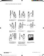
Page 8: ... BRIDGES WITH INDIVIDUAL MOTOR DRIVEN END TRUCKS P N 11532620 REV AA September 2018 Figure 2 Operator Hand Signals OPERATING PRECAUTIONS CONTINUED CMK_12322 Yale Rotating Axle End Truck Parts 11532619 REV AD_mec indd 7 10 16 18 2 07 PM ...

Page 9: ...RE OPERATIONAL INSPECTION elsewhere in this manual PRE SHIFT INSPECTION A pre shift inspection shall be performed by the crane operator or designated person at the beginning of each shift or the first time the crane is used during each shift This is a visual and operational inspection to ensure the equipment is in good working order Items to be checked include limit switches brakes electrical equi...

Page 10: ...le and Maintenance Report found elsewhere in this manual Items to be inspected include but are not limited to 1 All functional operating mechanisms for misadjustment interfering with crane operation 2 Operating parts for excessive wear 3 All safety devices for malfunction 4 All connections and mountings for loose bolts nuts and other fasteners for tightness 5 All structural members and welds for d...

Page 11: ...ONE NEAR THE BRIDGE GIRDER S OR SIMULTANEOUSLY AT EACH END OF THE TRUCK BETWEEN THE WHEEL AND THE GIRDER S JACKING OR LIFTING ONLY ONE END OF THE TRUCK MAY PERMANENTLY DAMAGE THE CRANE 3 Remove load from wheel axle This can be accomplished by jacking or lifting at the girder s Jacking or lifting only one end of the truck may permanently damage the crane 4 If working on driver wheel unplug motor le...

Page 12: ...d by turning the setting bolts hollow screws clockwise out of the brake coil housing 5 Tighten the fixing screws to the appropriate torque 6 Re check and measure the air gap in multiple locations to check for appropriate spacing Repeat the steps as needed until the desired air gap spacing is uniform and consistent all the way around the brake Brake Air Gap Inspection for FIR Gearmotors Procedure 1...

Page 13: ...erse order disassembly 6 Turn power onto crane and test for proper operation BRAKE REMOVAL AND REPLACEMENT If brake air gap exceeds the maximum allowed or is not functioning properly the brake may need to be replaced Follow these instructions 1 Turn power off to crane and lock out 2 Unplug motor leads open motor conduit box and disconnect brake leads from rectifier 3 Remove brake cover 4 Remove re...

Page 14: ... does not constitute a safety hazard before allowing unit to operate When corrective action is completed describe and note date in this column DATE Motor Gears Bearings Wheels Trucks Girders Connections Footwalk Handrail Motor Motor Brake Mechanical Load Brake Overload Clutch Couplings Gears Shafts Bearings Upper Block Lower Block Hook Throat Opening l X Record Hook Throat Opening Hoist Rope l Rop...

Page 15: ...sepower voltage phase and frequency when ordering replacement parts For motors gear cases and electrical components give complete nameplate data WARNING Using commercial or other manufacturer s parts to repair the Yale Hoist may cause load loss TO AVOID INJURY Use only Yale supplied replacement parts Parts may look alike but Yale parts are made of specific materials or processed to achieve specifi...

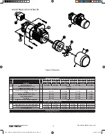
Page 16: ...3489001 2 2 Rail Sweep 88 mm tread 23488806 2 2 23488902 2 2 23489002 2 2 45492701 2 2 10 M10 1 50 SHCS 11802729 4 4 11802729 4 4 11802729 4 4 11802729 8 8 11802729 8 8 11 M10 Flat Washer 11803101 4 4 11803101 4 4 11803101 4 4 11803101 8 8 11803101 8 8 12 M10 Hi Collar Lock Washer 11803203 4 4 11803203 4 4 11803203 4 4 11803203 8 8 11803203 8 8 13 Bumper R1 11680704 2 2 11680704 2 Bumper R2 116807...

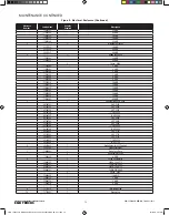
Page 17: ... Complete Brake Kit 180VDC 190 200 230V 380 460V 1 45152055 45152059 45152061 45152063 Complete Brake Kit 250VDC 575V 1 45152056 45152060 45152062 45152064 4 Fan Kit where applicable 1 45152075 45152077 45152078 33295051 5 Shroud Kit 1 45152080 45152082 45152083 33295055 6 Mating Easy Connect Plug where applicable 1 11829301 ABM Complete Gearmotor Assembly 7 190volt 3phase 50Hz 208 230volt 3phase ...

Page 18: ...ck 0 55 kW hp 160 mm Truck 0 75 kW 1 hp 200 mm Truck 1 2 kW 1 hp 260 mm Truck 1 55 kW 2 hp 260 mm Truck 2 2 kW 3 hp 305 mm Truck 3 7 kW 5 hp Part Number Part Number Part Number Part Number Part Number Part Number 1 Mounting Hardware Kit 1 45319150 45319151 45319152 45319153 45319153 N A 2 Rectifier Repair Part 190V 1 45319165 45319167 45319165 N A Rectifier Repair Part 208 230V 1 45319165 45319167...

Page 19: ...t Fuses 600V 11695210 10 AMP 11695212 12 AMP 11695220 20 AMP 11695225 25 AMP 11695230 30 AMP 11695235 35 AMP 11695250 50 AMP 11695260 60 AMP 11695270 70 AMP 11695280 80 AMP 11695290 90 AMP 2 1 Main Fuse Base 11695303 30 AMP 11695313 60 AMP 11695323 100 AMP 3 Replacement Fuses 600V 11695210 10 AMP 11695212 12 AMP 11695220 20 AMP 11695225 25 AMP 11695230 30 AMP Figure 9 Electrical Enclosure 2 7 4 9 ...

Page 20: ...ariable Frequency Drive 45199723 2 HP 230V 45199724 3 HP 230V 45199725 5 HP 230V 45199726 7 5 HP 230V 45199727 10 HP 230V 45199742 2 HP 460V 45199743 3 HP 460V 45199744 5 HP 460V 45199745 7 5 HP 460V 45199746 10 HP 460V 45334652 2 HP 575V 45334653 3 HP 575V 45334654 5 HP 575V 45334655 7 5 HP 575V 45334656 10 HP 575V 6 33310931 1 Brake Relay For VFC Control 33311996 Surge Surpressor 7 11696402 1 Br...

Page 21: ... BRIDGES WITH INDIVIDUAL MOTOR DRIVEN END TRUCKS P N 11532620 REV AA September 2018 FIGURE 10 INTERCONNECTION WIRING DIAGRAM MAINTENANCE CONTINUED CMK_12322 Yale Rotating Axle End Truck Parts 11532619 REV AD_mec indd 20 10 16 18 2 07 PM ...

Page 22: ... ordering parts always furnish Hoist Serial Number Catalog Number Motor Horsepower Voltage Phase Frequency and Rated Load of Hoist on which the parts are to be used PARTS AND SERVICES ARE AVAILABLE IN THE UNITED STATES AND IN CANADA Parts for your hoist or trolley are available from your local authorized repair station For the name of the nearest parts or service center visit our website www cmwor...

Page 23: ...GLE DOUBLE GIRDER TOP RUNNING BRIDGES WITH INDIVIDUAL MOTOR DRIVEN END TRUCKS P N 11532620 REV AA September 2018 Notes CMK_12322 Yale Rotating Axle End Truck Parts 11532619 REV AD_mec indd 22 10 16 18 2 07 PM ...

Page 24: ...OR FROM ANY COURSE OF DEALING OR USE OF TRADE ALL OF WHICH ARE HEREBY EXPRESSLY DISCLAIMED C IN NO EVENT SHALL SELLER BE LIABLE TO BUYER OR ANY THIRD PARTY WITH RESPECT TO ANY GOOD OR REPLACEMENT PART WHETHER IN CONTRACT TORT OR OTHER THEORY OF LAW FOR LOSS OF PROFITS OR LOSS OF USE OR FOR ANY INCIDENTAL CONSEQUENTIAL SPECIAL DIRECT OR INDIRECT DAMAGES HOWSOEVER CAUSED SELLER S MAXIMUM LIABILITY T...

Reviews: