5
6
SINGLE & DOUBLE GIRDER TOP-RUNNING BRIDGES
WITH INDIVIDUAL MOTOR DRIVEN
END TRUCKS
P/N: 11532620 REV. AA
September 2018
OPERATING PRECAUTIONS CONTINUED
NOTICE
If default settings for the bridge’s variable frequency
control, inverter, does not meet your specific requirements
it can be re-programmed. Programming of the inverter
shall be done by a qualified crane technician per the
manufacturer’s instruction manual. Each crane has a
maximum speed setting based on its capacity, span, duty
classification, etc.
Do NOT exceed maximum speed for
which the crane was specified when ordered.
STEP 5.
The trolley motion buttons are typically labeled “Left” and “Right”.
The hoist motion buttons are typically labeled “Up” and “Down”.
Practice and become acquainted with these controls.
NOTICE
Since a variety of hoist/trolley combinations may be used
with this type of bridge crane, refer to the manufacturer’s
instruction manual for this equipment and the specific
details on its operation.
STEP 6.
Once the operator(s) are acquainted and comfortable operating the
crane and the hoist/trolley, they shall learn the Pre-Shift inspection
procedure. Refer to the INSPECTION section of this manual.
WARNING
If, when depressing the hoist "Up" button, the hook should
lower - STOP AT ONCE - Do not attempt to operate
again. Report this condition to the proper supervisor for
correction with the instructions furnished with your hoist
manual by a qualified crane technician.
Set lower limit switches of the hoist and insure proper functioning
per the Hoist Manufacturer's Manual.
When operating the hoist in the up direction CAREFULLY OBSERVE
the relationship of the hook block and the bottom of the hoist frame.
The hoist upper limit switch, when working properly, should cause
the hoist up motion to stop and/or reverse direction.
WARNING
Do not contact or strike the hoist frame with the hook
block. If the hoist motion is not interrupted by the limit
switch, stop the hoist by removing your finger from
the button and/or depressing the STOP button. Do not
attempt further operation until the limit switch is operable.
Consult the Hoist Manufacturer's Instructions.
NOTICE
Jogging is the rapid and repeated pressing of a motion
pushbutton (hoist, trolley or bridge) to get the equipment
to move in short increments or “inching”. Although jogging
may be necessary to position a load, excessive jogging
will cause premature wear and failure of motors, brakes
and controls. It will also cause the motors to quickly
overheat, resulting in their thermal protection to disable
bridge motion until cooled.
WARNING
THIS EQUIPMENT IS NOT DESIGNED OR SUITABLE
AS A POWER SOURCE FOR LIFTING, LOWERING, OR
TRANSPORT OF PERSONS.
OPERATING THE CRANE
Once the crane has successfully passed its Start-up
and Pre-Operational (Initial) inspection, and all the crane
operators have been successfully trained and/or licensed, it
is now ready to be placed into service.
WARNING
Do not operate a crane, hoist or trolley having unusual
vibrations, sounds, warnings or with anything wrong or
apparently wrong. Danger may be present that the crane
operator cannot see. Determine and correct the cause of
the unusual conditions and make certain that the crane
can be operated SAFELY.
STEP 1.
Turn power on to the crane, disconnects and mainline. If not already
done so, perform Pre-Shift Inspection, refer to the Inspection
Section of this manual.
STEP 2.
Move the crane to the load making certain the load hook is high
enough to clear any obstruction in its path. Position the hoist and
trolley so that the load hook is centered over the load. Lower the
load hook for load attachment. For larger sized loads, the use of a
rigging or load director may need to be used to direct the lift and
movement of the load. This person should use the proper hand
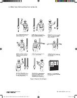
signals as shown in this manual. The crane operator should respond
only to the signals of the designated person directing the load,
except for emergency stop as shown in Figure 2.
WARNING
Prior to attaching or lifting a load, know the weight of
the load and the below the hook lifting devices (spreader
or lifting beams, magnets, grabs, slings, etc.). The total
weight of the load and lifting devices shall not exceed the
rated capacity of the hoist and/or crane.
STEP 3.
Attach load to load hook. Slowly raise the hook until the slack has
been taken out of the below the hook devices. When the floor man
signals and the operator is satisfied the load is secure in the sling, lift
the load slowly until clear. Now, hoisting speed can be increased and
maintained until the load is clear of all obstructions or the floor man
gives the signal to stop.
STEP 4.
Starting slowly and increasing speed as distance permits, move
the bridge toward the point where the load is to be lowered.
Decelerate and stop by releasing the push button. Final spotting is
accomplished by pressing the button to the first step to creep into
position.
STEP 5.
Learn to judge the stopping distance of the bridge and trolley, both
with light and full loads. This will enable you to “spot” loads with the
minimum amount of jogging and excessive load swing.
CMK_12322 Yale Rotating Axle End Truck Parts 11532619-REV AD_mec.indd 6
10/16/18 2:07 PM


