4
Installation
03.2018
29
ba
-o
.2
.6
.0
-us
-1.
1-
y
|
A
11
86
75
01
R
ev
A
A
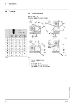
4.3.5
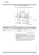
Monorail trolley (UE-S776)
with YKE/SKE, 4PS wire rope hoist (four-fall)
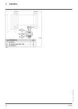
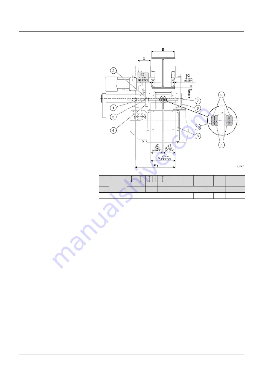
Fig. 18
Ø D Trolley
c
f/2
x
y z max Tightening
torque
[in]
INP IPE IPB
"
[in]
[lb
f
ft]
7.9 UE-S776
B = 7.3…19.7
in
B+3.6 0.059 3.7 7.4
1.9
155
Tab. 11
1.
Check flange width
“B”
and clearance
c ± 0.079 in.
against Tab. 11 and set trolley to
beam width if necessary. Ensure that the connection piece (square tube) (6) is in the
center (of dimension
“c”
) between the trolley side cheeks (
z1 = z2
).
2.
After unscrewing nuts (3) together with nuts (2), adjust clearance
c ± 0.079 in.
and
tighten nuts (3).
3.
Do not distort plate (10). Tighten nuts (5) lightly and then unscrew by a quarter turn.
Lock nuts (9) against nuts (5) with a torque spanner (see table above).
4.
Tighten nuts (3) with a torque spanner to the specified tightening torque (see table
above).
5.
Clearance
“c”
results in a flange play of
f/2 +0.039 in.
on each side. If necessary,
correct flange play by means of clearance
“c”
.
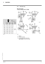
Installation if end of runway is freely accessible
1.
Slide trolley onto end of runway and check play f/2.
Installation if end of runway is not accessible
1.
Loosen nuts (3) on threaded bolts (1) in the square tube of the trolley side cheeks (4)
and unscrew by dimension
“x”.
2.
Push trolley side cheeks (4) apart in parallel up to the unscrewed nuts (3) until
dimension
B+y
or
c+x
is reached, and lift trolley onto runway from below.
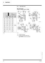
3.
Slide trolley onto the bottom flange of the runway beam on the axle keep plate side
(8) and secure against shifting.
4.
Push trolley side cheeks (4) back to nuts (2), retighten nuts (3).
5.
Check track gage
c ± 0.079 in.
and play of guide rollers
f/2
.
6.
Tighten nuts (3) with a torque spanner to the specified tightening torque (see table
above).


