7
Inspection and maintenance
03.2018
71
ba
-o
.2
.6
.0
-us
-1.
1-
y
|
A
11
86
75
01
R
ev
A
A
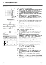
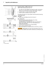
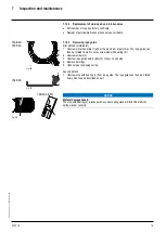
The clearances between the switching points for operational and emergency hoist limit
switches are set for normal operating conditions, however they can be increased if
necessary.
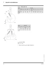
Fig. 79
*1 Effective hook path
7.10.4
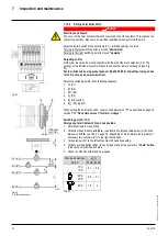
Testing emergency hoist limit switch, version 2
1.
Test at slow speed without load.
2.
Activate the
“up”
button
on the control pendant carefully, observing the hoisting
motion, until the hoist limit switch disconnects in top operational hook position (B↑).
3.
Activate the override button (S260) in the co
ntrol and at the same time the “up”
button until the emergency hoist limit switch disconnects (A↑). If the hoist does not
continue to move, the emergency hoist limit switch has already switched off in step 1
and the operational hoist limit switch is not working.
4.
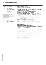
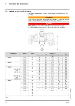
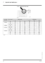
Minimum clearance
“a”
between bottom hook block and the nearest obstacle, see
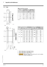
tab. 36. or the hook dimension
C -2.4 in.
, see Tab. 37, page 76 must be maintained
at least, depending on which dimension is larger
(see page 72, section
7.10.6 “Setting hoist limit swi
t
ch”
).
5.
Activate the override button (S261) in the control panel and at the same time the
“down”
button
to leave the limit switch area.
6.
Activate the “down”
button on the control pendant carefully, observing the hoisting
motion, until the hoist limit switch disconnects in bottom operational hook position
(B↓).
7.
Activate the override button (S262) in the control and at the same time the
“up”
button
until the emergency hoist limit switch disconnects (A↓). If the hoist does
not continue to move, the emergency hoist limit switch has already switched off in
step 5 and the operational hoist limit switch is not working.
8.
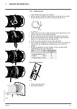
Minimum clearance between rope guide (S) and clamping claws (K) for rope
anchorage
= 0.79 in
, see Fig. 79, if necessary reset hoist limit switch
(see page 72, section
7.10.6 “Setting hoist limit swi
t
ch”
).
9.
Activate the override button (S261) in the control panel and at the same time the
“up”
button
to leave the limit switch area.
7.10.5
Testing operational hoist limit switch, version 2
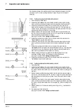
1.
Test without load.
2.
Activate the
“up” button
on the control pendant carefully, observing the hoisting
motion, until the hoist limit switch disconnects in the highest operational hook position
(B↑). Ensure that the hoist switches over to slow speed (B↑↑) before reaching cut
-off
point (B↑).
3.
Minimum clearance
a+2.4 in.
between bottom hook block and the nearest obstacle,
see Tab. 34, or the hook dimension
“C”
, see Tab. 37, page 76 must be maintained at
least, depending on which dimension is greater. If necessary reset hoist limit switch,
see page 72.
4.
Activate the “down” button on the control pendant carefully, observing the hoisting
motion, until the hoist limit switch disconnects in the highest operational hook position
(B↓). Ensure that the hoist switches over to slow speed (B↓↓) before reaching cut
-off
point (B↓).
5.
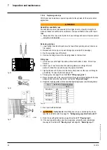
Minimum clearance 4.7 in between swi
tching points (B↓) and (A↓), (
see illustration
on the left)
6.
If necessary reset hoist limit switch
(see page 72, section
7.10.6 “Setting hoist limit swi
t
ch”
).


