4
Installation
03.2018
23
ba
-o
.2
.6
.0
-us
-1.
1-
y
|
A
11
86
75
01
R
ev
A
A
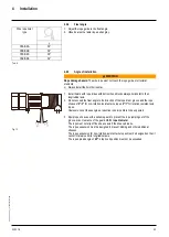
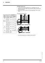
4.2.4
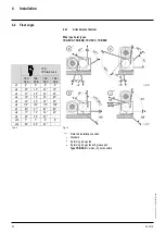
Fleet angle
Wire rope hoist
type
γ
YKA/SKA
39°
YKB/SKB
39°
YKC/SKC
39°
YKE/SKE
39°
Tab. 6
1.
Adjust the rope guide to the fleet angle.
2.
Observe also the radial rope exit angle γ.
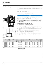
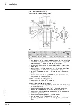
4.2.5
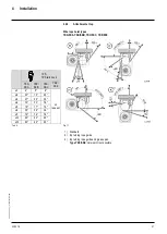
Angle of installation
WARNING
Rope damage hazard.
The wire rope must not touch the rope guide or structural
elements.
➢
Always install the hoist horizontal.
Fig. 13
1.
Install hoists with rope drives with bottom hook blocks always horizontal to their
longitudinal axis.
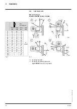
2.
Do not exceed the fleet angle to the direction of the rope drum groove and the rope
sheave of
4°/3°
for non-rotation-resistant wire ropes,
2°/1°
for rotation-resistant wire
ropes.
However even at these angles a reduction in service life is to be expected.
3.
Equip rope sheaves with a suitable guard to prevent the rope jumping out of the
groove, max. clearance of the guard
<0.5 × rope diameter
.
The rope must not slip off the sheave axle if the sheave breaks.
The rope suspension must be designed to prevent kinking and other additional
stresses.
The rope suspension for non-rotation-resistant wire ropes must be designed so that it
cannot rotate around its longitudinal axis.
The rope spread angle of
45°
in top hook position must not be exceeded.


