6
An ASSA ABLOY Group brand
P/N AYRT-220-INST-FUL Rev A
INSTALL LOCK
Install Latch
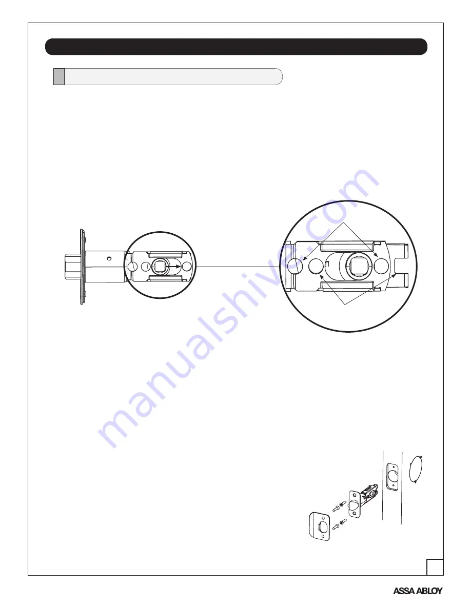
A. Remove the latch (Fig. 1) and strike plate from the packaging.
NOTE
: Latch ships with backset in 2-3/8" position (Fig. 1).
Backset
is the measurement from door edge to center
of 2-1/8" diameter hole (see template supplied with lock).
If required, pull to extend to 2-3/4" backset position (Detail 1A).
NOTE
: Different holes are used for (2) through bolts depending on backset (see Detail 1A).
Figure 1
Detail 1A
2-3/8" through bolt posts
2-3/4" through bolt posts
The lock is packed representative of how it will install on the door.
Before installing the lock on the door:
B. Install latch bolt in door.
1. Attach with two (2) M4 x 25.4mm screws supplied.
C. Install strike on the door frame, using two (2) M4 x 25mm
screws supplied, making sure to allow for the latch to be
centered in the strike.
NOTE
: The latch bolt (and strike) can be installed in only one of two ways -
with the bevel (slope) of latch facing out or facing in
while standing
outside of the door.
If the door opens
in
, the bevel will face the outside; if the doors opens
out
, the
bevel will face in.
The strike plate is installed according to the orientation of the latch bolt. See
Figures 1 & 2 for an example of a RH door that opens in.
NOTE
: Make sure door has been prepped according to specifications in template included
with lock.
(4) M4 x 25.4mm
Flat Head
Combination Screws
NOTE
: Both latch face and strike plate have adhesive-backed covers to
prevent marring and should be removed upon installation.
Figure 2


