9
Before you start
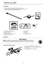
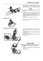
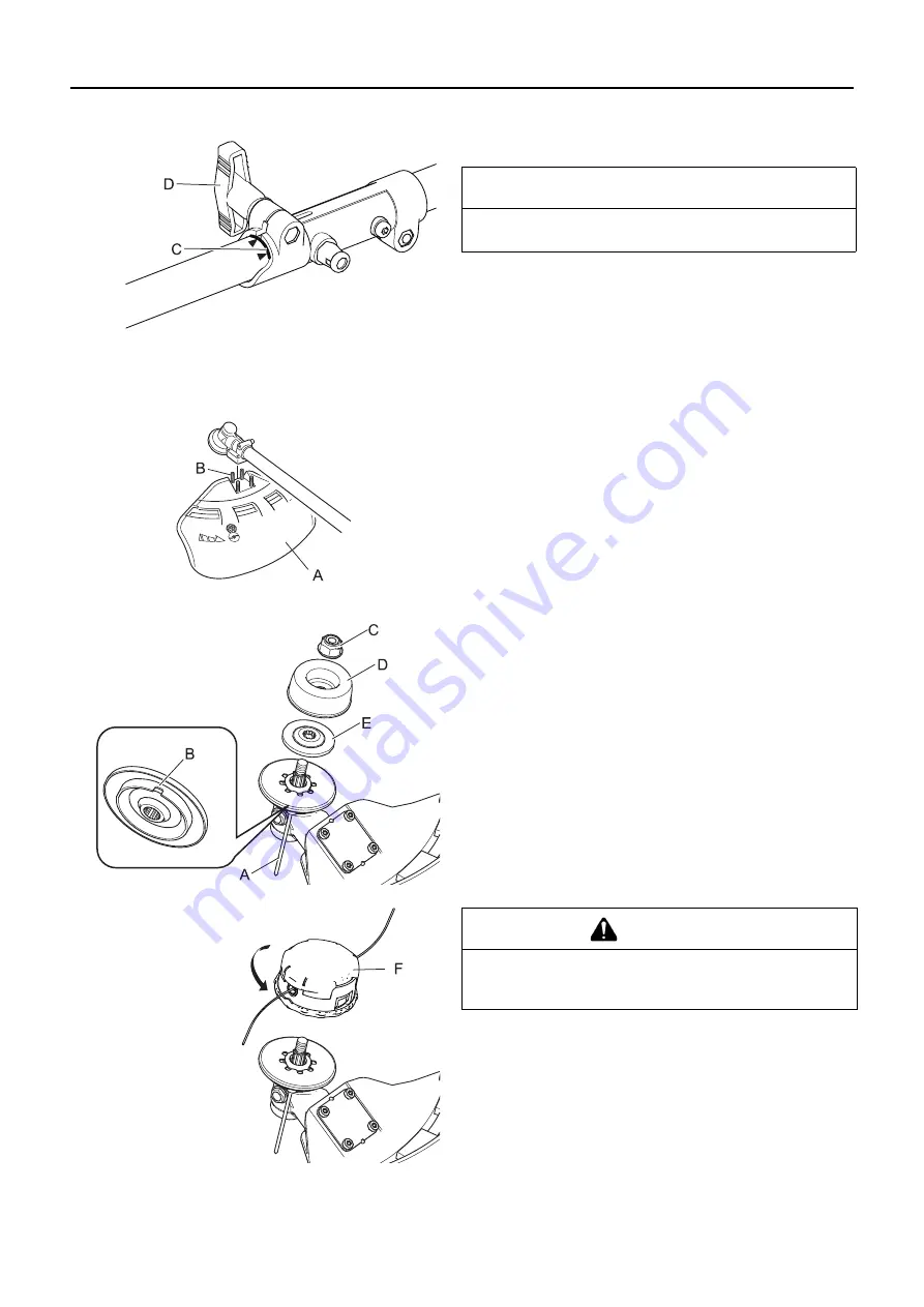
4. Carefully fit attachment drive shaft assembly into coupler (B)
to decal assembly line (C), making sure that the inner lower
drive shaft engages into the square upper drive shaft socket.
5. Rotate locator pin (A) 1/4 turn clockwise to engage lower
shaft hole. Insure locator pin is fully engaged by twisting low-
er drive shaft. Locator pin should snap flush in coupler. Full
engagement will prevent further shaft rotation.
6. Secure lower shaft assembly to coupler by tightening clamp-
ing knob (D).
7. To disassemble, reverse assembly instructions.
Installation of shield
1. Fit shield (A) to mounting portion of angle transmission and
tighten 4 bolts (B).
Installing nylon line cutting head
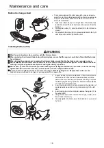
1. Insert locking tool (A) into a hole located on the right side of
angle transmission while forcing retainer spring to the left
side.
2. Insert locking tool further into blade retainer fixing slot (B) to
fix output shaft.
3. Using the socket wrench, remove the nut (C), cup (D), and
lower blade retainer (E).
∗
Nut, cup, and lower blade retainer are not used with a nylon
line cutting head.
4. Thread nylon line cutting head (F) onto shaft (anticlockwise)
until it is tight.
5. Remove locking tool.
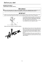
NOTE
Lower bearing housing and head assembly must be in line with
the motor unit.
CAUTION
Fix output shaft securely using locking tool in order to
prevent it form rotating when nylon cutting head is
mounted.
Summary of Contents for ECHO MTA-TB
Page 2: ......
Page 23: ...21 1Notes and rear cover MEMORANDUM ...
Page 68: ...22 1Notizen und hintere Umschlagseite NOTIZEN ...
Page 69: ...23 NOTIZEN ...
Page 91: ...21 1Note e quarta di copertina MEMORANDUM ...
Page 113: ...21 1Notas y contraportada MEMORANDO ...
Page 115: ......

