Chapter 8 Using your robot
8.4.2 Infrastructure
The operations available from this menu are used to configure the robot's installation in the
field.
See also:
(page 82)
•
(page 115)
•
(page 116)
•
(page 118)
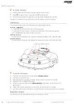
8.4.2.1 Peripheral wires
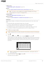
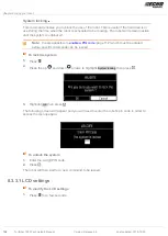
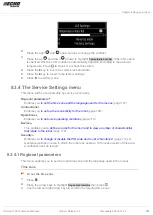
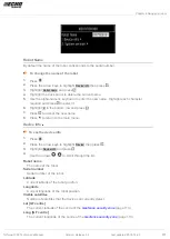
This schedules the "Wires Setting" screen.
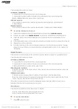
Wire CH#
A list of defined wires is presented, with the corresponding channel number. The list of
parcels associated with the wire is listed below it.
Select a wire and press to see the
(page 115).
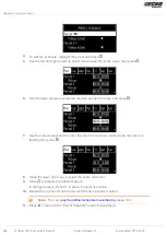
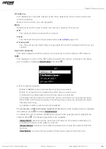
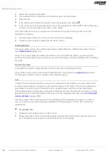
Create new wire
Enables you to
(page 116).
8.4.2.1.1 Wire properties
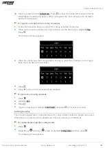
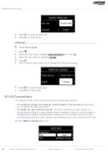
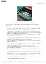
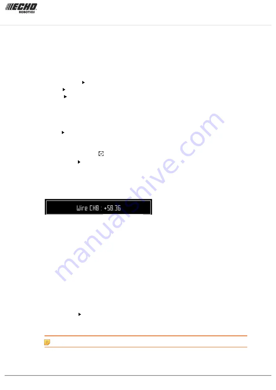
Wire id and magnetic distance
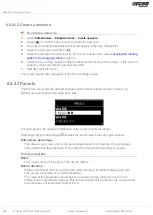
The identification of the wire in terms of the associated channel is displayed. In addition
the current value and sign of the magnetic distance between the robot and the wire is
indicated.
Signal channel
The signal (frequency) channel for the peripheral wire. This corresponds to the channel
set using the rotating switch in the charging station
(page 44). In the case of a multi-field
installation, each wire used, must be assigned to a specific channel.
Reverse phase
The sign of the phase on the inside of the field is opposite to that on the outside. This is
how the robot can detect whether it has crossed the peripheral wire. The phase should be
positive inside the field.
You can see whether this is the case by examining the magnetic distance value shown at
the top of the screen. If the value is positive the phase is correct. If it is negative you need
to check this option to reverse the phase.
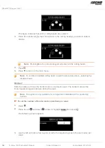
Delete Wire CH#
This option only appears if there is more than one wire defined. It allows you to delete the
current wire.
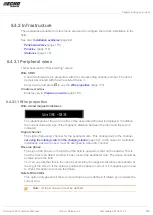
Note: At least one wire must be defined.
Turfmow 1000 Technician's Manual
Version: Release 3.5
Last updated: 2018-12-20
115

