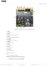
Chapter 7 Installation
Switch
1
2
3
4
5
6
7
8
ON
Always
Never
TM2000
accepted
Ball
Picker
accepted
TM1000
accepted
YES
YES
Never
OFF
Never
Always
TM2000
NOT
accepted
Ball
Picker
NOT
accepted
TM1000
NOT
accepted
NO
NO
Always
7.2 Installing the peripheral wire
This chapter describes the installation requirements and considerations for the peripheral
wire.
Note: Specific considerations are required when installing multiple wires (fields).
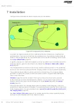
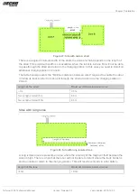
The peripheral wire is shown in
Figure 28: Components of an installation
(page 38).
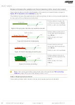
The boundary of the area to be mowed lies within the complete site. The distance between
the peripheral wire and this boundary will vary, depending on the characteristics of the site.
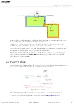
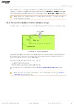
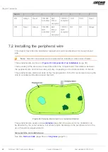
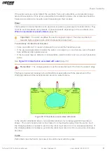
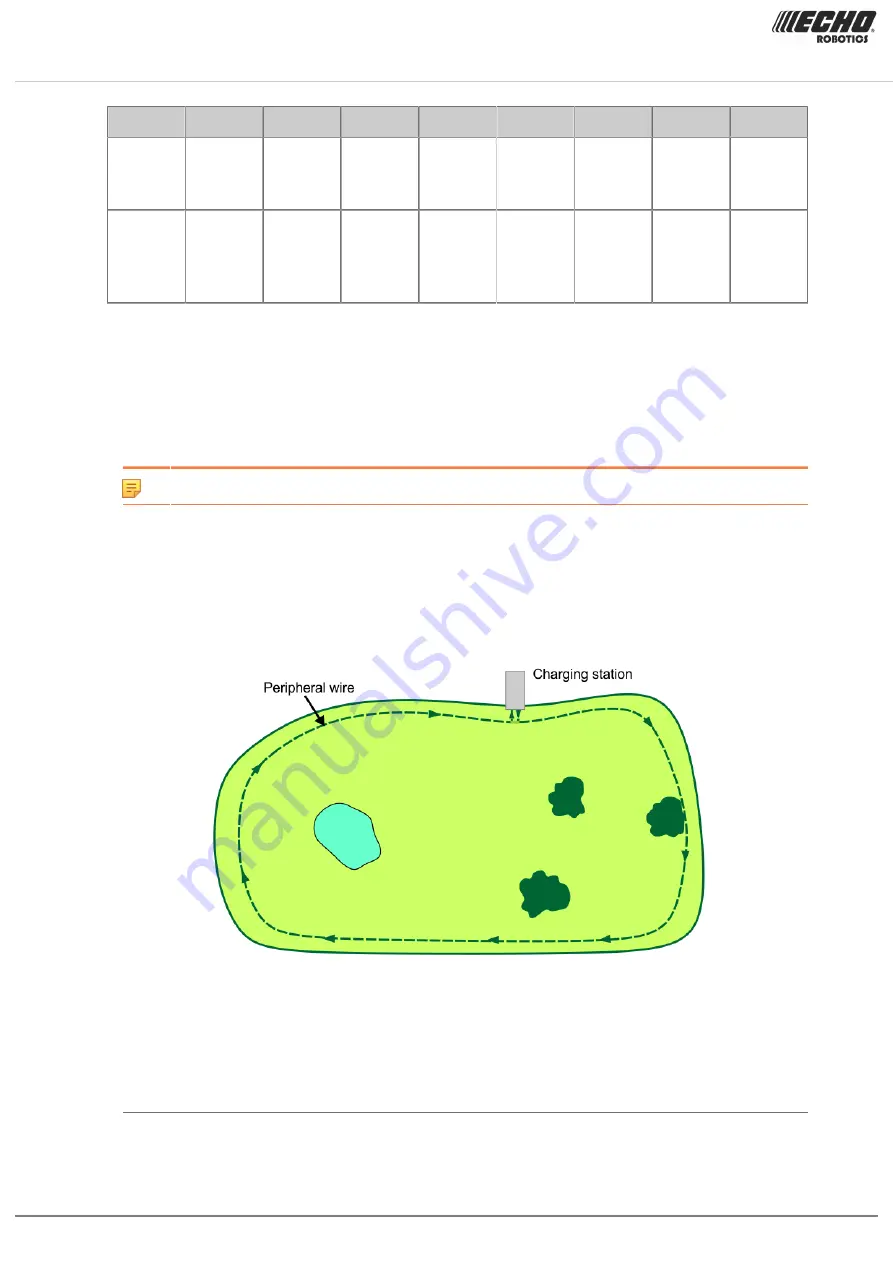
The peripheral wire starts and ends at the charging station. Echo EU recommends laying the
wire in a clockwise direction around the field.
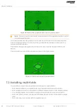
Figure 40: Peripheral wire laid in a clockwise direction
The peripheral wire needs to take
(page 52) into account. Some obstacles can
be detected by the sonar sensors, but others require deviations in the peripheral wire or the
use of islands or pseudo-islands.
General Site considerations
(page 50) and
(page 51).
48 Turfmow 1000 Technician's Manual
Version: Release 3.5
Last updated: 2018-12-20

