


OPERATION MANUAL
OPERATION MANUAL
OPERATION MANUAL
OPERATION MANUAL
YAMADA AIR
YAMADA AIR
YAMADA AIR
YAMADA AIR----OPERATED DIAPHRAGM PUMPS
OPERATED DIAPHRAGM PUMPS
OPERATED DIAPHRAGM PUMPS
OPERATED DIAPHRAGM PUMPS
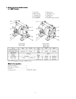
NDP-5 series
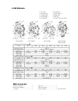
DP-10/12 series
NDP-10/12 series
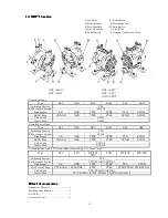
NDP-15 series
NDP-20 series
NDP-25 series
NDP-40 series
NDP-50 series
NDP-80 series
DP-F series
Doc. No.
NDP002U-18
Issue
1998-6
Revised
2008-12