1
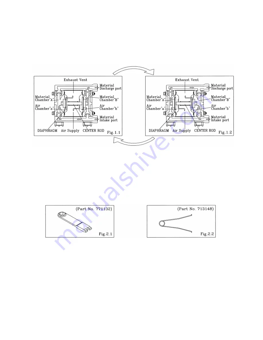
1.Principles of operation
There are two diaphragms fixed to the center rod, one at each end. When compressed air is supplied to air
chamber b (right side, see Fig. 1.1), the center rod moves to the right, the material in material chamber B
is pushed out, and at the same time material is sucked into material chamber A.
When the center rod is moved full-stroke to the right, the air switch valve is switched, compressed air is
sent to air chamber a (left side, see Fig.1.2), and the center rod moves to the left. The material in
material chamber A is pushed out, and at the same time material is sucked into material chamber B.
Through repetition of this operation, material is repeatedly taken in and discharged out.
2.Tools, etc.
2.1 General tools
▪
Socket wrenches
10mm( NDP-5 ), 13mm( NDP-15 )
▪
Open-end wrenches
10mm ( NDP-5 ), 13mm( NDP-15 ), 21mm( NDP-15 )
▪
Plyer
2.2 Special tools (sold separately)
▪
Cap and
disk remover
▪
Sleeve remover
Purpose: Removing the center disk of
Purpose: For removing sleeves
FP
□
and FVT and FDT types
2.3 Misc.
▪
Assembly oil
Turbine oil none addition class 1( equivalent to ISO VG32 grade )
▪
Nuts
M6
X
1( NDP-5 ), M8
X
1.25( NDP-15 )
▪
Grease
Urea grease grade (NLGI) No.2
3.Ordering Replacement parts
For accurate and speedy shipment of parts, be sure to order the right parts for your model to distributor
Indicate the part numbers, descriptions, and quantities.


