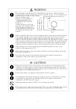
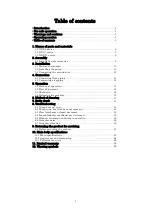
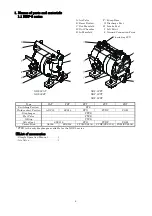
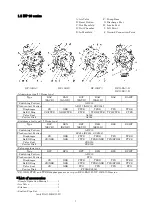
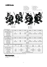
background image


Doc. No.  NDP174U-22 


OPERATION MANUAL 


YAMADA AIR-OPERATED DOUBLE DIAPHRAGM PUMP 


NDP-5 series 
DP-10 series 

NDP-15 series 

Summary of Contents for NDP-20 series

Page 1: ...Doc No NDP174U 22 OPERATION MANUAL YAMADA AIR OPERATED DOUBLE DIAPHRAGM PUMP NDP 5 series DP 10 series NDP 15 series ...

Page 2: ...el NDP DP G and AD series excluding NPT thread type Directive 2006 42 EC Directive 2014 30 EU NDP E and DP E series EN ISO 12100 2010 EN 809 1998 A1 2009 Manufacturer Name of company YAMADA CORPORATION Address 1 1 3 Minami Magome Ota ku Tokyo 143 8504 Japan Importer Authorized Representative in EU Name of company YAMADA EUROPE B V Address Aquamarijnstraat 50 7554NS Hengelo Ov the Netherlands Origi...

Page 3: ...ron polypropylene polyvinylidene fluoride depending on the model you have selected according to the type of fluid to be pumped The diaphragms are made of rubber based or plastic based materials For safe operation This document contains information vital for safe and efficient operation of this product Before using the pump be sure to read this document carefully particularly the warnings and cauti...

Page 4: ...orking pressure at the specific temperature of the liquid being pumped Air pressure and discharge pressure must not exceed the allowable working pressure If air pressure and discharge pressure exceed the allowable working pressure it may cause liquid leaks damaged pump casings or diaphragms and could cause a fatal accident When moving this product make sure that the internal pressure is released I...

Page 5: ... other causes of ignition If a diaphragm is damaged fluid will gush out together with air from the exhaust port Do NOT leave gasoline or solvent etc that contains waste at the work site Machinery and other equipment near the place of installation of this product should be properly insulated to prevent conduction with each other Do NOT operate heating devices that create flames or have heating fila...

Page 6: ...sion resistance it may result in damaging the product or leakage of fluid When working in the vicinity of pumping of fluid with this product be sure to wear protective gear goggles mask etc When using this product observe the relevant regulatory rules concerning fire prevention labor safety standards etc If you have any questions on the operation of this product method of connection or installatio...

Page 7: ...5 1 Method of operation 15 5 2 Flow adjustment 15 5 3 Shutdown 16 5 4 Releasing the pressure 16 6 Method of cleaning 17 7 Daily check 18 8 Troubleshooting 8 1 Pump does not run 18 8 2 Pump runs but fluid does not come out 18 8 3 Flow discharge volume decreased 18 8 4 Liquid leaks from exhaust port silencer 19 8 5 High air consumption during in operation 19 8 6 Irregular noise 19 8 7 Irregular vibr...

Page 8: ... NDP 5FAT NDP 5FPT NDP 5FST NDP 5FVT NDP 5FDT Type FAT FST FPT FVT FDT Switching Portion PPS Fluid contact Portion ADC12 SCS14 PPG PVDF POM Diaphragm PTFE Flat Valve PTFE O Ring PTFE Valve Seat SUS316 PPG PVDF POM Center Disk A5056 SUS316 PPG SUS304 PVDF SUS304 POM SUS304 PTFE is the only diaphragm available for the NDP 5 series List of accessories Simple Operation Manual 1 Air Valve 1 excluding F...

Page 9: ...ainless steel type Drum type Type BSC BSC D BSN BSN D BST BST D BSH BSH D BSS BSH T Switching Portion ADC12 Fluid contact Portion SCS14 SCS14 SUS304 Diaphragm CR NBR PTFE TPEE TPO TPEE Ball O Ring CR NBR NBR PTFE TPEE NBR TPO EPDM PTFE Valve Seat SUS316 Center Disk SUS316 Polypropylene type Type BPC BPN BPT BPH BPS BPH T Switching Portion ADC12 Fluid contact Portion PPG Diaphragm CR NBR PTFE TPEE ...

Page 10: ...pe Type BSC BSN BST BSH BSS BSH T Switching Portion PPS Fluid contact Portion SCS14 Diaphragm CR NBR PTFE TPEE TPO TPEE Ball O Ring CR NBR NBR PTFE TPEE NBR TPO EPDM PTFE NBR Valve Seat SUS316 Center Disk SUS316 Polypropylene type Polyvinylidene fluoride type Type FPC FPN BPN FPT FVT BPT FPH BPH FPS BPS Switching Portion PPS Fluid contact Portion PPG PVDF Diaphragm CR NBR PTFE TPEE TPO Flat Valve ...

Page 11: ... on 1 Names of parts and materials With some models these are already installed CAUTION All of the connection parts are capped or taped for shipment Remove the caps and tapes When installing accessories make sure that no foreign matter falls into the product as it could cause malfunction of the switching portion Use PTFE tape when installing air valve See 10 1 Main specifications Remember that the...

Page 12: ...E Try to keep the suction lift as short as possible To protect diaphragm from abnormal breakage inlet pressure must be kept below the following values PTFE diaphragm 0 02 MPa height 2 m During operation 0 05 MPa height 5 m Not in operation Other diaphragms 0 1 MPa height 10 m Condition with fresh water under ambient temperature Remember to provide sufficient space around the pump for maintenance T...

Page 13: ...c provide protective measures installation of a pit or sensors etc in consideration of possible leakage of fluid and post warning signs at necessary places For details see the applicable operating caution on P 2 and P 4 WARNING If using the pump with a flammable fluid or in a flammable environment read the applicable operating caution on P 3 NOTE Arranging outside exhaust Remove the silencer Conne...

Page 14: ...connect ground wires to the connected piping and any other connected equipment For details see the applicable operating caution on P 3 When the pump is operated without a ground wire or otherwise not properly grounded friction between parts and abrasion caused by some fluids flowing inside the casing may generate static electricity Also depending on the type of fluid being pumped and the installat...

Page 15: ...mp to stop larger particles Otherwise such particles may cause a malfunction If depending upon the place of pump installation the volume of the pumped fluid changes drastically install a relief valve on the discharge side and bring the pressure down below the maximum permissible value If owing to a change in the volume of fluid the pressure inside the pump exceeds the maximum permissible pressure ...

Page 16: ...d be equal to the inlet port of the pump to supply enough air to run the pump The air compressor should be able to provide adequate air flow to the pump Attach the compressor as close as possible to the pump considering operability and stability of air pressure If you use a solenoid valve as the air valve be sure it is a three way valve When the valve is closed the internal compressed air of the p...

Page 17: ...enly In case of use lubricator must be used turbine oil none addition class 1 turbine oil equivalent ISO VG32 grade for lubricants Do not apply lubricants more than required and also do not use any other lubricants which designated on this instruction manual This may cause of pump problem and there is danger of serious bodily damage 5 2 Flow adjustment Adjust the flow valve on the discharge side F...

Page 18: ...verloaded and this may cause damage such as bending of the center rod After finishing your work purge the remaining fluid from the pump see 6 Method of cleaning 5 4 Releasing the pressure 1 Make sure that the air valve of the pump is closed 2 Shut down the air compressor or close the valve on the air supply side of the peripheral equipment 3 Close the flow valve on the discharge side start slowly ...

Page 19: ...ch different hoses to the suction side and the discharge side for cleaning 4 Be ready with a vessel with cleaning solution select cleaning solution appropriate for the type of fluid pumped and then connect the suction side and the discharge side hoses of the pump 5 Operate a pump by starting air pressure slowly and let the cleaning solution circulate for sufficient cleaning 6 Finally flush with cl...

Page 20: ...ck and clean the fluid piping The pump is clogged with sludge Disassemble the casing check and clean 8 2 Pump runs but fluid does not come out Cause Action to be taken The suction lift or discharge head is long Confirm the piping configuration and shorten the length The discharge side fluid piping including the strainer is clogged with sludge Check and clean the fluid piping The valve on the sucti...

Page 21: ...issible diameter Disassemble the casing check and clean 8 7 Irregular vibration Cause Action to be taken The supply air pressure is too high Adjust the supply air pressure The spool oscillates and occur ball chattering Adjust the supply air pressure and exhaust pressure Connection parts and pump mounting are loose Check each connection part and tighten the bolts If disassembly is required refer to...

Page 22: ... 8 Air Connection Supply Port Rc 1 4 NPT 1 4 Rc 1 4 Rc 1 4 NPT 1 4 Exhaust Port Rc 3 8 NPT 3 8 Rc 3 8 Rc 3 8 NPT 3 8 Operating Air Pressure 0 2 0 7 MPa 0 2 0 7 MPa 1 Maximum Discharge Pressure 0 7 MPa 0 7 MPa 1 Discharge Volume cycle 2 50 mL Maximum Discharge Volume 20 L min 18 L min 17 L min Maximum Air Consumption 300 L min ANR 250 L min ANR Slurry Limitation 1 mm or less Limitation of Viscosity...

Page 23: ... 0 5 Pa s or less Operating Temperature Range Temperature Ambient 0 70 C Temperature Liquid Diaphragm materials NBR CR 0 70 C TPEE EPDM 0 80 C FKM TPO PTFE 0 100 C 0 60 C A weighted emission sound pressure level 4 84 dB 87 dB A weighted sound power level 5 94 dB 97 dB Weight 4 1 kg 6 3 kg 3 5 kg 4 3 kg 1 Maximum air pressure for non metallic pumps decreases with temperature See 21 page of Temperat...

Page 24: ... 25 112 110 105 155 94 35 155 AIR INLET EXHAUST LIQUID OUTLET LIQUID INLET 4 Φ7 Rc1 4 NPT1 4 Rc1 4 NPT1 4 Rc1 4 NPT1 4 Rc3 8 NPT3 8 98 97 90 89 35 154 93 82 151 88 57 58 147 110 110 25 LIQUID OUTLET LIQUID INLET AIR INLET EXHAUST 4 Φ7 Rc1 4 NPT1 4 Rc1 4 NPT1 4 Rc1 4 NPT1 4 Rc3 8 NPT3 8 10 2 Appearance and dimensions 10 2 1 NDP 5 series NDP 5FAT NDP 5FST NDP 5FPT FVT FDT FVT ...

Page 25: ...3 8 146 181 92 142 20 20 192 124 107 85 237 35 179 AIR INLET LIQUID INLET EXHAUST LIQUID OUTLET Rc1 4 NPT1 4 Rc3 8 NPT3 8 4 Φ9 Rc3 8 NPT3 8 Rc3 8 NPT3 8 147 167 195 92 112 25 25 192 105 107 85 196 29 151 AIR INLET LIQUID INLET EXHAUST LIQUID OUTLET 4 Φ9 Rc1 4 Rc3 8 NPT1 4 NPT3 8 Rc3 8 NPT3 8 Rc3 8 NPT3 8 10 2 2 DP 10 series DP 10BA DP 10BS DP 10BP ...

Page 26: ...75 Φ17 20 192 109 107 85 1146 20 179 LIQUID OUTLET G2 M63 4 AIR INLET LIQUID INLET Rc3 8 Rc3 8 Rc3 8 Rc1 4 122 220 134 65 105 105 188 170 71 83 269 45 195 145 112 LIQUID OUTLET AIR INLET EXHAUST Rc1 4 NPT1 4 Rc3 8 NPT3 8 Rc1 2 NPT1 2 4 Φ7 LIQUID INLET Rc1 2 NPT1 2 DP 10BA D DP 10BS D 10 2 3 NDP 15 series NDP 15BA ...

Page 27: ... 4 Φ7 105 115 195 71 83 297 205 180 127 122 135 66 185 54 EXHAUST AIR INLET LIQUID INLET LIQUID OUTLET Rc1 2 NPT1 2 Rc1 4 NPT1 4 Rc3 8 NPT3 8 Rc1 2 NPT1 2 4 Φ9 220 NDP 15BS NDP 15FP BP FVT CAUTION Due to improvement or modification of products dimensions may change without notice Please contact your distributor our regional office for detailed information ...

Page 28: ...26 10 3 Performance curve 10 3 1 NDP 5 series 10 3 2 DP 10 series NDP 5 series DP 10BA BS DP 10BA D BS D DP 10BP 10 3 3 NDP 15 series NDP 15BA BS NDP 15FP BP FVT ...

Page 29: ...rocedure Fig 10 1 Conditions a Supplied air pressure Maintaining preset pressure b Liquid pumped Fresh water c Temperature Ambient d Condition of suction Flat suction 0 meter head e Measuring system System A Converting weight of discharged fluid to volume System B By liquid meter ...

Page 30: ...on of the component parts of the product 4 Irregularity arising from repair made by other than by our firm our regional office dealer or authorized service personnel 5 Malfunction arising from modification of the product by other than authorized service personnel 6 Wear and tear of parts that must be regularly replaced in the course of normal operation such as diaphragms center disk valve seats ba...

Page 31: ...29 12 Warning symbols BEWARE HIGH TEMPERATURE ELECTRIC SHOCK POISON FLAMMABLE CORROSION EXPLOSION General warnings cautions and danger notifications FIRE STRICTLY PROHIBITED ...

Page 32: ...受伤以及泵出现故障的原因 绝对禁止拉连接在泵上的软管来移动泵 这可能导致泵和软管破损 3 2 产品的设置 1 参照Fig 3 1A D 研讨适合的泵的设置场所 请确保其设置空间 NOTE 设置时请尽可能减小吸入扬程 压入使用时 为防止隔膜反转 请设置在下列数值以下 PTFE隔膜 运转时0 02 MPa 高度2 m 停止时0 05 MPa 高度5 m 其他隔膜 0 1 MPa 高度10 m 清水 常温时 为便于维护保养及修理 请确保泵周围要有足够的作业空间 材料吸入口以及排出口的方向可分别逆向设置 更换方法请参照修理要领书 从泵排出的气体含有垃圾 在排出的垃圾影响环境的场所使用时 请将其排出到 不影响其环境的地方 2 请将泵移动到设置的场所 3 固定泵时 请使用安装基座橡胶垫同时进行拧紧固定 Fig 3 1 排气 空气 空气 空气 空气 ...

Page 33: ...令时等 请根据需要进行妥当的隔音处置 各产品的噪音值请参照P20后 面的 10 1主要参数 移送危险液剂 高温 易燃 强酸性等 时 设想到液剂流出的情况 在进行防护设置 设置地沟和 防护箱 传感器检知等 的同时 请在必要的位置设置警告标志 详细内容请阅读P2及P4的 使用 注意事项 警告 在易燃液剂及其环境中使用泵时 请阅读P3的 使用注意事项 NOTE 外部排气方法 请拆下消音器 将带有接地线的软管与泵的排气口相连 请将软管前端安装在消音器上 请使用与排气口相同口径的软管 软管长度在5m以上时 请与购买时的销售店或封底记载的营业所联系 请在软管的前端设置地沟 防护箱等 Fig 3 2 警告 设想隔膜破损 软管前端有液剂流出 因此请务必设置地沟 防护箱等 详细内容请阅读P2的 使用 注意事项 泵的排气要排出在没有人和动物出没的安全场所 NOTE 操作空气管道 利用电磁阀进行控制时 推荐使用...

Page 34: ...1 各部的名称 和材料 中的外观图 但NDP 5FPT NDP 15FP 除外 b 同样 泵的辅机类设备与配管也要设置接地线 c 请使用断面积为2 0 mm2 以上的接地线 Fig 3 3 警告 构成装置请务必设置接地线 详细内容请阅读P3的 使用注意事项 在未设置接地线的状态下如果运行本产品 则可能因滑动部位和移送液剂种类的不同 在套管内流动 时因摩擦而产生静电 从而导致泵可能带电 因移动的液剂或设置场所的环境 氛围及周围的设置物 等 不同 可能导致火灾和触电事故发生 接地线设置位置 ...

Page 35: ... 8504 Japan PHONE 81 0 3 3777 0241 FAX 81 0 3 3777 0584 E mail intl yamadacorp co jp Web www yamadacorp co jp YAMADA THAILAND CO LTD 41 79 Moo 6 Bangcha long Bangplee Sumutprakarn10540 Thailand PHONE 66 0 2 130 0990 FAX 66 0 2 130 0993 E mail sales yamada th com 202007 2441 NDP174U ...

Page 36: ... 8504 Japan PHONE 81 0 3 3777 0241 FAX 81 0 3 3777 0584 E mail intl yamadacorp co jp Web www yamadacorp co jp YAMADA THAILAND CO LTD 41 79 Moo 6 Bangcha long Bangplee Sumutprakarn10540 Thailand PHONE 66 0 2 130 0990 FAX 66 0 2 130 0993 E mail sales yamada th com 202107 2569 NDP174U ...

Reviews: