8
▪
Draw the center disk to one side (exclude B_H, B_S type
cf.Fig.5.9).
▪
And install the out chamber. Tighten the bolts temporarily.
▪
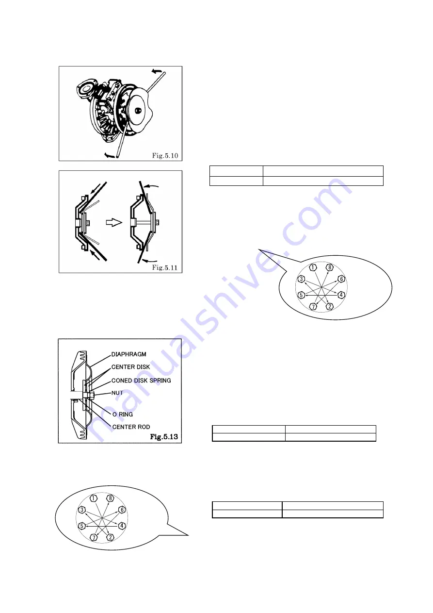
Grip the inside center disk using crowbars and draw it to the
opposite side, then turn the diaphragm over.
(exclude B_H, B_S type) [Fig.5.10, 5.11]
▪
And install the out chamber. Tighten the bolts temporarily.
▪
After installation of the out chambers on both sides, place the
pump on a flat surface and stand the pump upright for further
assembly.
Tightening torque for out chamber.
BA_, BS_, BF_
29 ft-Ibf {40 N-m}
BP_, BV_
26 ft-Ibf {35 N-m}
<NOTE>
▪
Make sure there is no dust on the seal surface in order to
prevent seal damaged.
▪
Be careful not to damage the R portion of the air chamber using
a crowbar, etc.
▪
Tighten the bolts gradually in a diagonal sequence with even
torque. (cf. Fig.5.12)
■
B_T type
For installation, see [Exploded View] on the separate sheet and install in the reverse order of disassembly.
▪
Apply assembly grease to the center rod, and insert it into the
main body.
▪
Keep the convex side to the outside (cf. Fig.5.13).
▪
Put the O rings to both sides of the diaphragm. (cf. Fig.5.13)
▪
Tighten the center disk using the PP wrench(special tool: Part
No. 771868) for the BPT, BVT type. Apply proper Thread locker
to the thread of center disk.
(No coned disk springs and nuts are needed.)
Tightening torque for center rod
BAT, BST, BFT
43 ft-Ibf {60 N-m}
BPT, BVT
36 ft-Ibf {50 N-m}
▪
Tighten the out chamber temporarily at first.
After installation of the out chambers on both sides, place the
pump on a flat surface and stand the pump upright for further
assembly.
Tightening torque for out chamber
BAT, BST, BFT
29 ft-Ibf {40 N-m}
BPT, BVT
26 ft-Ibf {35 N-m}
<NOTE>
▪
Make sure there is no dust on the seal surface in order to
prevent seal damaged.
▪
Replace the PTFE O ring by new one.
▪
Tighten the bolts gradually in a diagonal sequence with even
torque. (cf. Fig.5.14)
Fig.5.12
Fig.5.14


