


7
5.3 Installation
■
B
□
H, B
□
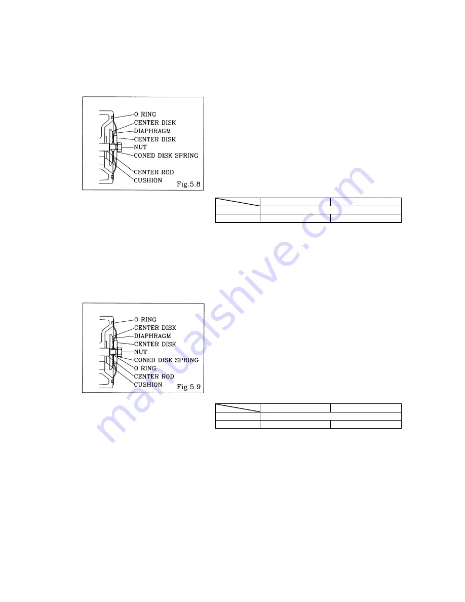
S, FPH, FPS types
For installation, see [Exploded View] on the separate sheet and install in the reverse order of disassembly.
▪
Apply grease to the center rod, and insert it into the main
body.
▪
Keep the convex side to the outside.
▪
Tighten the center disk using the open-end wrenches for the
NDP-15FP
□
, BPS. (No coned disk springs and nuts are
needed.)
▪
Tighten the out chamber temporarily at first.
▪
After installation of the out chambers on both sides, place
the pump on a flat surface and stand the pump upright for
further assembly.
Tightening torque for center rod and out chamber
Center
rod
Out
chamber
NDP-5 7.5
N•m
NDP-15
14 N•m
12 N•m
<NOTE>
▪
Make sure there is no dust on the seal surface in order to
prevent seal damaged.
▪
Tighten the bolts that balance should be equal from both
side on diagonal line with even torque.
■
B
□
C, B
□
N, B
□
T, FPC, FPN, F
□
T types
For installation, see [Exploded View] on the separate sheet and install in the reverse order of disassembly.
▪
Apply grease to the center rod, and insert it into the main
body.
▪
Keep the marking “LIQUID” to liquid end for CR, NBR
diaphragms.
▪
Keep the convex side to the outside for PTFE diaphragm.
Install the O ring (cf. Fig.5.9).
▪
Tighten the center disk using the open-end wrenches.
▪
After installation of the out chambers on both sides, place
the pump on a flat surface and stand the pump upright for
further assembly.
Tightening torque for center rod and out chamber
Center
rod
Out
chamber
NDP-5 7.5
N•m
NDP-15
14 N•m
12 N•m
<NOTE>
▪
Make sure there is no dust on the seal surface in order to
prevent seal damaged.
▪
Replace the PTFE O ring by new one.
▪
Tighten the bolts that balance should be equal from both
side on diagonal line with even torque.


