background image


6.Pilot valve Assembly, Guide and Bushing 


 6.1 Removal 


NDP-5 


Remove the diaphragm and center rod etc.(see [5.1 

    Removal] on P.5) 


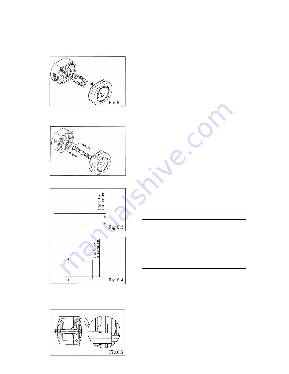
Remove the main body. [Fig.6.1] 


Draw out the pilot valve assembly. [Fig.6.1] 


Remove the packing and bushing. [Fig.6.1] 


NDP-15 


Remove the diaphragm and center rod etc.(see [5.1   


Removal] on P.5)                                                                                                         


Remove the body B. [Fig.6.2] 


Draw out the pilot valve assembly. [Fig.6.2] 


Remove the packing, bushing and guide. [Fig.6.2] 


 6.2 Inspection 


Bushing (NDP-5) [Fig.6.3] 
Measure the inside diameter, and if it is outside the usable   
range, replace the bushing. 


Usable range of bushing 

Ø

 10.1 ~

 Ø

 10.3 mm 


Guide ( NDP-15 ) [Fig.6.4] 

Measure the inside diameter, and if it is outside the usable   

range, replace the guide. 


Usable range of guide 

Ø

 14.1 ~

 Ø

 14.2 mm   


O ring, Packing   


If the O ring is worn out or cracked, replace it. 


Pilot valve assembly 


If the pilot valve is worn out or cracked, replace it. 


 6.3 Installation 


For installation, see [Exploded View] on the separate sheet and install in the reverse order of disassembly. 

The correct direction of the V packing 

<NOTE> 


Make sure there is no dust on the seal surface and the   

  seal is not damaged.                                                                             


Apply grease to packing. 


The open side of the V faces toward the diaphragm (air 

chamber).  


ig.6.2 

Summary of Contents for NDP-5 series

Page 1: ...MAINTENANCE MANUAL YAMADA AIR OPERATED DOUBLE DIAPHRAGM PUMP NDP 5 NDP 15 Doc No NDP 183M 09...

Page 2: ...ution described and operate the product in an improper manner there is danger of personal injury or property damage Furthermore to indicate the type of danger and damage the following symbols are also...

Page 3: ...2 Inspection Ball valve types 4 Flat valve types 4 4 3 Installation 4 5 Diaphragm and Center rod 5 1 Removal FAT FST BA BS BPS types 5 FP FV FDT types 6 5 2 Inspection 6 5 3 Installation B H B S FPH F...

Page 4: ...me material is sucked into material chamber B Through repetition of this operation material is repeatedly taken in and discharged out 2 Tools etc 2 1 General tools Socket wrenches 10mm NDP 5 13mm NDP...

Page 5: ...e guide flat valve and valve seat NDP 5 Fig 4 2 Remove the O ring valve guide ball and valve seat NDP 15 Fig 4 2 Turn over the main body assembly Fig 4 3 Remove the 4 retainer bolts from the in manifo...

Page 6: ...the in manifold removes NDP 5 Remove the O ring valve stopper flat valve and valve seat Fig 4 6 Turn over the main body assembly Fig 4 7 Pull out the bolt and remove the base and in manifold NDP 5 Rem...

Page 7: ...is worn out or cracked replace it Usable range of Flat valve NDP 5 2 5 3 1 mm NDP 15 4 3 5 0 mm Valve seat Fig 4 12 Measure the dimension shown at left and if it is outside the usable range replace t...

Page 8: ...f the center rod Fig 5 2 After the nuts on one side have been removed remove the center disk and diaphragm Remove the diaphragm center disk and center rod from the opposite side of the main body NOTE...

Page 9: ...in body NOTE When the diaphragms are removed the main body is separated 2 pieces For easy work leave bolts fastened temporarily before remove the diaphragms Fix a double nut to one end of the center r...

Page 10: ...the bolts that balance should be equal from both side on diagonal line with even torque B C B N B T FPC FPN F T types For installation see Exploded View on the separate sheet and install in the revers...

Page 11: ...outside the usable range replace the bushing Usable range of bushing 10 1 10 3 mm Guide NDP 15 Fig 6 4 Measure the inside diameter and if it is outside the usable range replace the guide Usable range...

Page 12: ...assembly If the seal ring is worn out or cracked replace C spool valve assembly Usable range of seal ring NDP 5 1 40 1 48 mm NDP 15 1 82 1 90 mm Sleeve Assembly Fig 7 5 Measure the inside diameter an...

Page 13: ...rial on daily inspecting a pump Retainer bolts from the out chamber Retainer bolts from the manifold NDP 5 FPT FVT FDT 7 5 N m 7 5 N m NDP 15 FP FVT FDT 12 N m 12 N m NOTE Tighten the bolts that balan...

Page 14: ...Manufactured by YAMADA CORPORATION INTERNATIONAL DEPARTMENT No 1 3 1 Chome Minami Magome Ohta Ku Tokyo 143 8504 Japan PHONE 81 0 3 3777 0241 FAX 81 0 3 3777 0584 201710 NDP183M...

Reviews: