background image

7

NO.

PARTS NO.

DESCRIPTION

Q'TY

1

681170

Silencer

1

2

802630

Air motor

1

3

803358

Lower pump

3-1

702971

Pin

3

3-2

706091

Union

1

3-3

702985

Suction tube

1

3-4

702986

Rod

1

3-5

702975

Union

1

3-6

702974

Stop washer

1

3-7

702976

Spring

1

3-8

630313

Ball

1

3-9

803355

Cylinder assembly

1

3-10

702977

Washer

2

3-11

632754

Spring pin

1

3-12

706072

Foot tube

1

3-13

702980

Valve ring

1

3-14

706399

Plunger rod

1

3-15

771404

Foot valve

1

3-16

702982

Valve seat

1

3-17

830407

Valve adapter assembly

1

3-18

702983

Tube

1

3-19

702984

Plate

1

3-20

627010

Nut

1

3-21

632019

Cotter pin

1

4

770409

Packing

1

5

711650

Out tube

1

NO.

PARTS NO.

DESCRIPTION

Q'TY

1

852498

Pump assembly

1

2

800766

Check valve

1

3

695034

High-pressure hose

1

4

851985

Grease gun

1

5

680743

Air coupler

1

6

830138

Gun holder

1

7

705841

Handle

1

8

702779

Grease nipple

1

9

631013

Plain washer

2

10

682276

Nut

2

11

706076

Cabinet

1

12

602296

Pan-head screw

1

13

704570

Clamping nut

2

14

831098

Base frame

1

15

681767

Caster (with brake)

2

16

680136

Caster

2


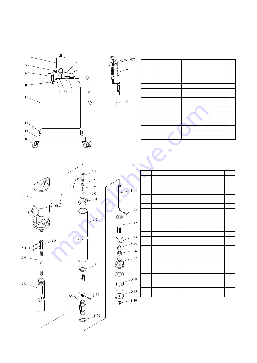
6.  Parts Disassembly Drawing and Parts List 

6.1 880870 SKR-55 

Parts List 


6.2  852498 Pump assembly 

Parts List


Summary of Contents for SKR-55 880870

Page 1: ...GREASE LUBRICATOR SKR 55 MODEL No 880870 WARNING Prior to operating this pump be sure to read this operation manual for safety After reading the manual please keep it at hand any time for your quick reference INSTRUCTION ...

Page 2: ...ly be sure to observe the contents of the following description In this manual warnings and cautions are indicated by using symbols These symbols are intended to prevent death or serious injury that may be caused to the operator or those who are around the product and damage that may be caused to the articles that are around the product as well as to use the product safely and correctly Each symbo...

Page 3: ...his product should not move unexpectedly Also do not use or leave this product in a slope or any unstable locations This product moves freely when the caster is not locked and the damage only accident and the facilities pollution etc might occur Such a secondary disaster becomes a responsibility on the user side Make ground connection when working with flammable material or in explosive atmosphere...

Page 4: ... and dust It is likely to lead to the pollution of the material Watch your step around this product to avoid tripping over the base and casters Be careful about your hands when mounting dismounting the cabinet or installing a pail The edges of the cabinet and pail may cause hand injury Also be careful about your posture when moving the pump or lifting the cabinet to avoid back injury Material rema...

Page 5: ...tion of the Lower Pump 2 3 Preparations before Operation 3 4 How to Operate the Machine 4 5 Maintenance and Inspection 5 1 Troubleshooting and corrective measures 5 5 2 Maintenance and inspection 5 5 3 Disassembly and assembly 6 6 Parts Disassembly Drawing and Parts List 6 1 880870 SKR 55 7 6 2 852498 Pump assembly 7 6 3 802630 Air motor 8 6 4 851985 Grease gun 9 7 Specification 10 8 Trouble Infor...

Page 6: ...ts 1 2 Contents of package The main devices and the accessories are packed in different cases Open the top part of the corrugated fiberboard case and check if the devices is not damaged and if accessories are all contained in the package ...

Page 7: ...ducted to the chamber B and the chamber A is conducted to the exhaust port so that the air piston is changed to go up 6 Thus the air motor continues its reciprocating motion automatically as long as the supply air is fed to it 2 2 Function of the Lower Pump 1 The lower pump integrated with the air motor traces the reciprocating motion of the air motor 2 The shovel performs mixing so that grease ma...

Page 8: ...it was Tighten the clamping nuts on both sides equally 4 Connect the attached high pressure hose and grease gun to the discharge port of the pump 5 When the air coupler is connected to the pump the pump and hose will be filled with grease After that the pump operation will stop 6 The first applied grease includes the internal air of the pump This is not a good condition Obtain a perfect condition ...

Page 9: ... the hydro chuck of the high pressure grease gun against the nipple to perform chucking as vertically as possible Fig 5 2 Pull the lever of the high pressure grease gun to supply grease The pump is automatically operated to supply grease When grease is normally injected old grease will be squeezed out from the groove or clearance bear the nipple 3 After completion of grease supply release the gun ...

Page 10: ...pressure between 0 3 and 0 7 MPa Operate the pump with the discharge side hose removed If the pump is operated the outlet valve of the hose is clogged If the pump is not operated the pump is defective Ask the dealer to repair it Check if grease is in the pail Supply grease Check if a cavity is produced in the suction tube Gather grease toward the middle The lower pump is defective Ask the dealer t...

Page 11: ...e and remove the air chuck and high pressure hose form the pump 2 Unscrew the pan head screw of the body supporter that fixes the pump Pull out the pump from above Fig 9 3 Fix the main body of the pump on the vise and set a spanner on the valve adapter Set a pipe wrench on the tube and unscrew the tube 4 Pull out the split pin that fixes the plate and unscrew the nut The plate can be removed Fig 1...

Page 12: ...830407 Valve adapter assembly 1 3 18 702983 Tube 1 3 19 702984 Plate 1 3 20 627010 Nut 1 3 21 632019 Cotter pin 1 4 770409 Packing 1 5 711650 Out tube 1 NO PARTS NO DESCRIPTION Q TY 1 852498 Pump assembly 1 2 800766 Check valve 1 3 695034 High pressure hose 1 4 851985 Grease gun 1 5 680743 Air coupler 1 6 830138 Gun holder 1 7 705841 Handle 1 8 702779 Grease nipple 1 9 631013 Plain washer 2 10 682...

Page 13: ...1 Packing 1 26 711384 Collar 1 10 701822 Valve seat 1 27 701816 Valve supporter 1 11 705659 Trip shoe 1 28 681768 Screw w spring 2 12 710950 Body 1 29 590085 Guide plate 1 13 706068 Spindle 1 30 701766 Tube gland 2 14 706067 Bushing 1 31 701765 Sleeve 2 15 640012 O ring 1 32 702582 Washer 2 16 706066 Gland housing 1 33 683629 O ring 1 17 770182 O ring 1 6 3 802630 Air motor Parts List NOTE If disa...

Page 14: ... 6 713638 Washer 1 7 711357 Rod 1 8 711352 Body 1 9 711351 Link 1 10 683201 Rivet 2 11 804911 Nozzle 1 12 685728 Cap 1 13 630314 Ball 1 14 711445 Spring retainer 1 15 711446 Spring 1 16 640011 O ring 1 17 710971 Union 1 18 802910 Swivel joint assembly 1 6 4 851985 Grease gun Parts List No 3 8 9 and No 10 are undissolution ...

Page 15: ...ler Plug PS 20PM 0 2 0 7 MPa A WEIGHTED SOUND PRESSURE LEVEL 1 86 dB A WEIGHTED SOUND POWER LEVEL 2 96 dB ENV TEMPERATURE 0 60 MATERIAL TEMP 0 80 13 5 kg 695034 High Pressure Hose 1 4 2 5m 851985 High Pressure Grease Gun 680743 Air Coupler PS 20PM 1 Measurement method of A weighted sound pressure level is based on ISO 1996 2 Measurement method of A weighted sound power level is based on ISO 3744 A...

Page 16: ...t enriches our repair services After filling it send it to us Trouble Information Fax Form Company name Name Department name Address Contact information Tel Fax Product name Model Duration of use 20 year month to year month SERIAL No LOT No Operation frequency Continuous Intermittent hour day week month Purchase date Sales outlet Machine conditions descriptions of the trouble ...

Page 17: ...d that may cause corrosion inflation or dissolution of the component parts of the product 4 Irregularity arising from repair made by other than by our firm our regional office dealer or authorized service personnel 5 Malfunction arising from modification of the product by other than authorized service personnel 6 Wear and tear of parts that must be regularly replaced in the course of normal operat...

Page 18: ...ATION INTERNATIONAL DEPARTMENT No 1 3 1 Chome Mimami Magome Ohta Ku Tokyo 143 8504 Japan PHONE 81 0 3 3777 0241 FAX 81 0 3 3777 0584 YAMADA EUROPE B V Aquamarijnstraat 50 7554 NS Hengelo 0 The Netherlands PHONE 31 0 74 2422032 FAX 31 0 74 2421055 ...

Reviews: