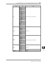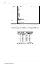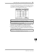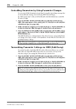
Controlling the DM1000 from a Video Editor
259
DM1000 Version 2—Owner’s Manual
Controlling the DM1000
from a V
ideo Editor
19
19 Controlling the DM1000 from a
Video Editor
This chapter describes the control functions, which enable you to control the DM1000 from
a video editor using the ESAM protocol.
About ESAM
ESAM (Editing Suite Audio Mixers) is the post-production standards for linking video edi-
tor to a mixing console. You can automate audio crossfade and switching operations that
are linked to video editing operations.
The DM1000 supports the ESAM Serial II Protocol (ESAM II) - Extended. For supported
commands, see page 264.
Connection Example
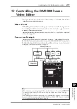
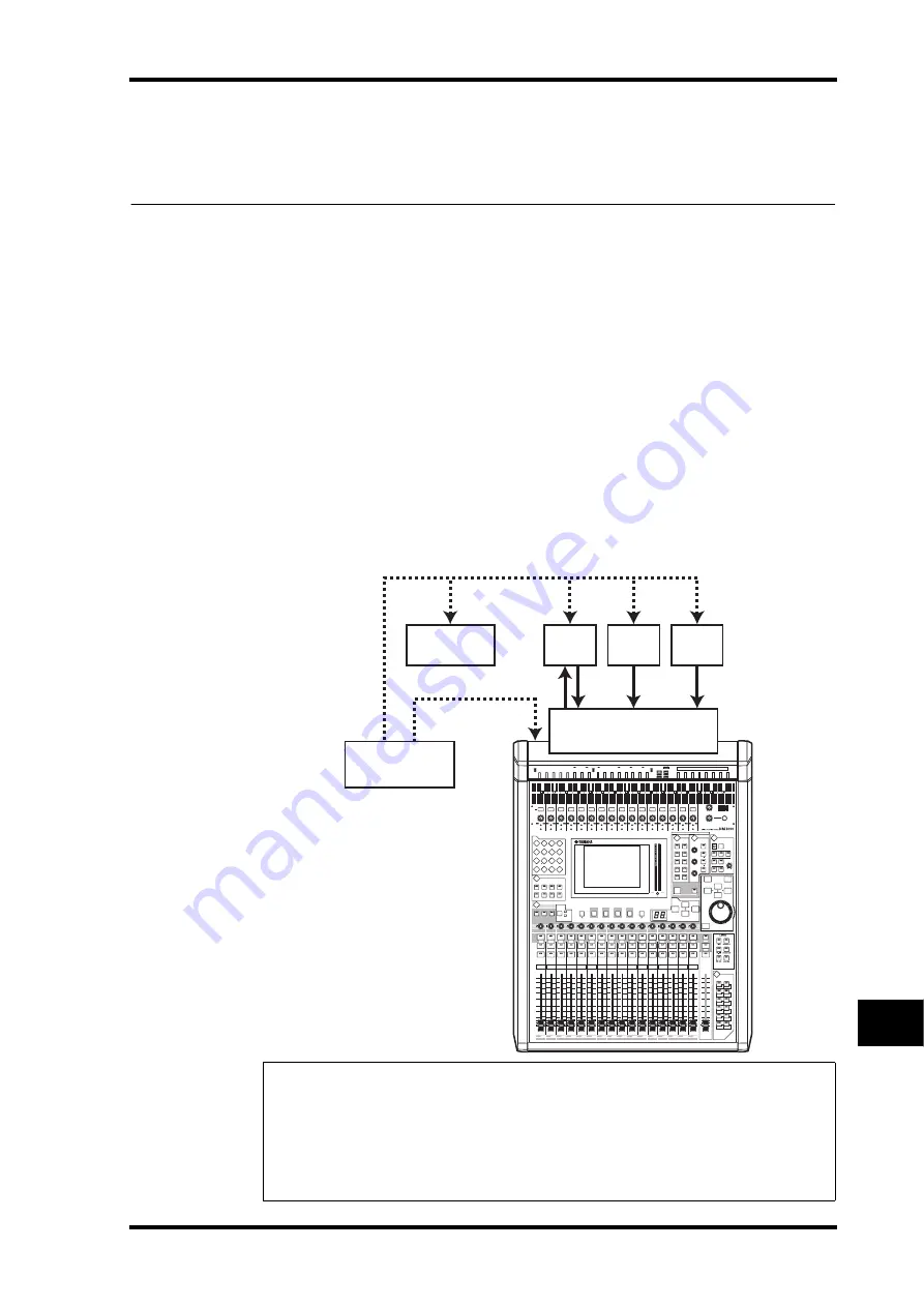
The following diagram illustrates an example of connecting a video editor and a VTR via
the DM1000. You need a dedicated cable to connect the DM1000’s REMOTE connector to
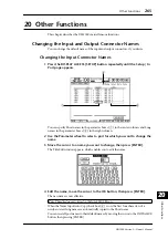
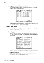
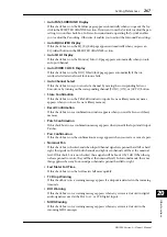
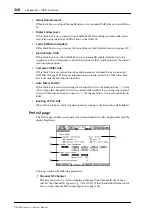
the video editor (page 264). For more information on the basic connections and setup, refer
to chapter 4 “Connections and Setup” on page 43.
Note:
• Use control room monitoring (page 119) to monitor the signals. First, set the OMNI OUT
connectors' signal routing to “CR-L/CR-R” using the Output Patch | Omni Out page
(page 113).
• The maximum output level of the OMNI OUT connectors is +24 dB. If you are connecting
a device with the maximum input level of +18 dB to an OMNI OUT connector, attenuate
the output signal using the attenuators (page 90).
AUX
PAN
DISPLAY
ASSIGN
ENCODER MODE
EQUALIZER
LOW
HIGH
GAIN
Q
FREQUENCY
LOW MID
HIGH MID
ROUTING
1
2
3
4
5
6
7
8
STEREO
DIRECT
DISPLAY
DISPLAY
SELECTED CHANNEL
16
BUS
8
32
48
15
BUS
7
31
47
14
BUS
6
30
46
13
BUS
5
29
45
12
BUS
4
28
44
1 1
BUS
3
27
43
10
16
15
14
13
12
1 1
10
20dB
ON
OFF
+48V
1
2
3
4
5
6
7
8
12
13
14
15
16
9
10
11
16
15
14
13
12
11
10
9
8
7
6
5
4
3
2
PEAK
SIGNAL
1
-16
-60
GAIN
-16
-60
GAIN
-16
-60
GAIN
-16
-60
GAIN
-16
-60
GAIN
-16
-60
GAIN
-16
-60
GAIN
-16
-60
GAIN
-16
-60
GAIN
-16
-60
GAIN
-16
-60
GAIN
-16
-60
GAIN
-16
-60
GAIN
-16
-60
GAIN
-16
-60
GAIN
-16
-60
GAIN
PEAK
SIGNAL
PEAK
SIGNAL
PEAK
SIGNAL
PEAK
SIGNAL
PEAK
SIGNAL
PEAK
SIGNAL
PEAK
SIGNAL
PEAK
SIGNAL
PEAK
SIGNAL
PEAK
SIGNAL
PEAK
SIGNAL
PEAK
SIGNAL
PEAK
SIGNAL
PEAK
SIGNAL
PEAK
SIGNAL
PAD
20dB
20dB
20dB
20dB
20dB
20dB
20dB
20dB
20dB
20dB
20dB
20dB
20dB
20dB
20dB
ON
OFF
+48V
ON
OFF
+48V
ON
OFF
+48V
ON
OFF
+48V
ON
OFF
+48V
ON
OFF
+48V
ON
OFF
+48V
ON
OFF
+48V
ON
OFF
+48V
ON
OFF
+48V
ON
OFF
+48V
ON
OFF
+48V
ON
OFF
+48V
ON
OFF
+48V
ON
OFF
+48V
0
5
10
15
20
30
40
50
60
70
50
40
30
20
15
10
+10
5
0
5
ON
SOLO
SEL
AUX
1
1
1
17
33
0
5
10
15
20
30
40
50
60
70
50
40
30
20
15
10
+10
5
0
5
ON
SOLO
SEL
AUX
2
2
2
18
34
0
5
10
15
20
30
40
50
60
70
50
40
30
20
15
10
+10
5
0
5
ON
SOLO
SEL
AUX
3
3
3
19
35
0
5
10
15
20
30
40
50
60
70
50
40
30
20
15
10
+10
5
0
5
ON
SOLO
SEL
AUX
4
4
4
20
36
0
5
10
15
20
30
40
50
60
70
50
40
30
20
15
10
+10
5
0
5
ON
SOLO
SEL
AUX
5
5
5
21
37
0
5
10
15
20
30
40
50
60
70
50
40
30
20
15
10
+10
5
0
5
ON
SOLO
SEL
AUX
6
6
6
22
38
0
5
10
15
20
30
40
50
60
70
50
40
30
20
15
10
+10
5
0
5
ON
SOLO
SEL
AUX
7
7
7
23
39
0
5
10
15
20
30
40
50
60
70
50
40
30
20
15
10
+10
5
0
5
ON
SOLO
SEL
AUX
8
8
8
24
40
0
5
10
15
20
30
40
50
60
70
50
40
30
20
15
10
+10
5
0
5
ON
SOLO
SEL
BUS
1
9
9
25
41
0
5
10
15
20
30
40
50
60
70
50
40
30
20
15
10
+10
5
0
5
ON
SOLO
SEL
0
5
10
15
20
30
40
50
60
70
50
40
30
20
15
10
+10
5
0
5
0
5
10
15
20
30
40
50
60
70
50
40
30
20
15
10
+10
5
0
5
0
5
10
15
20
30
40
50
60
70
50
40
30
20
15
10
+10
5
0
5
0
5
10
15
20
30
40
50
60
70
50
40
30
20
15
10
+10
5
0
5
0
5
10
15
20
30
40
50
60
70
50
40
30
20
15
10
+10
5
0
5
0
5
10
15
20
30
40
50
60
70
50
40
30
20
15
10
+10
5
0
5
ON
SOLO
SEL
ON
SOLO
SEL
ON
SOLO
SEL
ON
SOLO
SEL
ON
SOLO
SEL
ON
SOLO
SEL
BUS
2
26
42
AUTO
ON
SEL
STEREO
70
60
50
40
30
20
15
10
5
0
AUX
2
AUX
3
AUX
4
AUX
6
AUX
5
AUX
7
AUX
8
AUXSELECT
DISPLAY
AUX
1
FADER MODE
FADER
AUX
DISPLAY ACCESS
AUTOMIX
DIO
SETUP
UTILITY
MIDI
REMOTE
METER
VIEW
PAIR/GROUP
INPUT
OUTPUT
EFFECT
SURROUND DYNAMICS
SCENE
/
PAN/
INSERT/ DELAY
PATCH
PATCH
GRAB
SCENE MEMORY
STORE
RECALL
DISPLAY
USER DEFINED
KEYS
ENTER
INC
DEC
TALKBACK LEVEL
PHONES
LEVEL
0
10
0
10
PHONES
MONITOR
LEVEL
SOLO
CLEAR
2TR D1
2TR D2
DIMMER TALKBACK
MONITOR
STEREO
SLOT
BUS
DISPLAY
10
0
F
1
F
2
F
3
F
4
0
OVER
-2
-4
-6
-8
-10
-12
-14
-18
-24
-30
-36
-42
-48
-56
-72
0
OVER
-2
-4
-6
-8
-10
-12
-14
-18
-24
-30
-36
-42
-48
-56
-72
L
R
VTR1
(REC)
VTR2
VTR3
AES/EBU
REMOTE
ESAM II
Digital I/O card
MY16-AE or MY8-AE
Video editor
Video
switcher
Remote (D-sub 9-pin)
(D-sub 9-pin)
Summary of Contents for 006IPTO-F0
Page 42: ...42 Chapter 3 Operating Basics DM1000 Version 2 Owner s Manual ...
Page 52: ...52 Chapter 4 Connections and Setup DM1000 Version 2 Owner s Manual ...
Page 92: ...92 Chapter 7 Bus Outs DM1000 Version 2 Owner s Manual ...
Page 108: ...108 Chapter 8 Aux Sends DM1000 Version 2 Owner s Manual ...
Page 146: ...146 Chapter 11 Surround Functions DM1000 Version 2 Owner s Manual ...
Page 214: ...214 Chapter 16 Automix DM1000 Version 2 Owner s Manual ...
Page 385: ...DM1000 Block Diagram ...

