34
Chapter 3—Operating Basics
DM1000 Version 2—Owner’s Manual
Selecting Channels
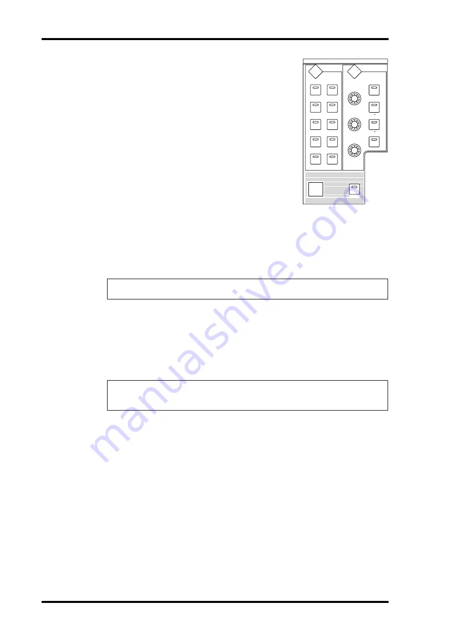
The SELECTED CHANNEL controls enable you to edit
main mix parameters for a channel selected from the Input
Channels and Output Channels (Aux Outs, Bus Outs, and
Stereo Out).
To select a channel for editing using the SELECTED
CHANNEL controls, follow the steps below:
1 Press the corresponding LAYER button to select a
layer that includes the desired channel (see
page 33).
2 Use the corresponding [SEL] button or fader to
select the desired Input or Output Channel.
The channel is selected and the [SEL] button indicator
lights up.
If the Fader Touch Sense parameter is enabled on the Setup | Prefer2 page (see page 268),
operating a fader selects the corresponding channel.
The Channel’s ID and Short name appear in the upper-left corner of the display. If the cur-
rently-displayed page contains a relevant channel parameter, the cursor moves to that
parameter automatically. If the currently-displayed page contains no such parameter, a page
that does contain such a parameter is selected automatically.
3 To select the Stereo Out, press the STEREO [SEL] button or touch the [STE-
REO] fader.
Repeatedly pressing the STEREO [SEL] button toggles between the Stereo Out left and Ste-
reo Out right channels.
If the currently-displayed page contains a relevant Stereo Out parameter, the cursor moves
to that parameter automatically. If the currently-displayed page contains no such parame-
ter, a page that does contain such a parameter is selected automatically.
Tip:
For paired Input or Output Channels, the channel for which you pressed the [SEL] button
is selected, and its indicator lights up. The [SEL] button indicator of the paired partner flashes.
Tip:
If the Auto Channel Select parameter is enabled on the Setup | Prefer1 page (see
page 266), operating a fader or Encoder, or turning on a [SOLO] or [ON] button selects the
corresponding channel.
EQUALIZER
LOW
HIGH
GAIN
Q
FREQUENCY
LOW MID
HIGH MID
ROUTING
1
2
3
4
5
6
7
8
STEREO
DIRECT
DISPLAY
DISPLAY
SELECTED CHANNEL
GRAB
Summary of Contents for 006IPTO-F0
Page 42: ...42 Chapter 3 Operating Basics DM1000 Version 2 Owner s Manual ...
Page 52: ...52 Chapter 4 Connections and Setup DM1000 Version 2 Owner s Manual ...
Page 92: ...92 Chapter 7 Bus Outs DM1000 Version 2 Owner s Manual ...
Page 108: ...108 Chapter 8 Aux Sends DM1000 Version 2 Owner s Manual ...
Page 146: ...146 Chapter 11 Surround Functions DM1000 Version 2 Owner s Manual ...
Page 214: ...214 Chapter 16 Automix DM1000 Version 2 Owner s Manual ...
Page 385: ...DM1000 Block Diagram ...

