36
Chapter 3—Operating Basics
DM1000 Version 2—Owner’s Manual
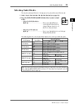
Selecting Encoder Modes
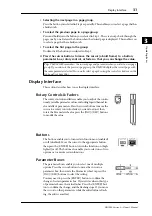
The function of Encoders (1–16) depends on the selected Layer and Encoder mode.
1 Select a layer that includes the desired channel (see page 33).
2 Press the corresponding ENCODER MODE button to
select an Encoder mode.
• When the [PAN] button indicator
lights up:
...............................................Encoders 1–16 function as
Pan controls for the
selected layer.
• When the [AUX] button indicator
lights up:
...............................................Encoders 1–16 function as Aux Send level con-
trols for the selected layer.
• When the [ASSIGN] button indicator
lights up:
...............................................Encoders control the parameters assigned to the
[ASSIGN] button for the selected layer. (See the
next section for more information on how to
assign parameters to the [ASSIGN] button.)
The following table shows the Encoder functions for each Layer and Encoder mode.
LAYER buttons
Encoder Mode
Channel Strip Encoder
1–8
9–16
[1-16] button
Pan
Input Channels 1–16 pan
Aux
Input Channels 1–16 Aux Send level
Assign
Assigned parameter
1
1. If ALT LAYER is assigned, the Encoder controls the parameters assigned to the faders of the layer that
is currently not selected (if Layer 1-16 is currently selected, the Encoder controls the parameters as-
signed to the faders in Layer 17-32; if Layer 17-32 is currently selected, the Encoder controls the pa-
rameters assigned to the faders in Layer 1-16).
[17-32] button
Pan
Input Channels 17–32 pan
Aux
Input Channels 17–32 Aux Send level
Assign
Assigned parameter
[33-48] button
Pan
Input Channels 33–48 pan
Aux
Input Channels 33–48 Aux Send level
Assign
Assigned parameter
[REMOTE 1] button
Pan
Operation depends on the selected target (see
page 215).
Aux
Assign
[REMOTE 2] button
Pan
Aux
Assign
[MASTER] button
Pan
No operation
Aux
Assign
Assigned parameter
AUX
PAN
DISPLAY
ASSIGN
ENCODER MODE
Summary of Contents for 006IPTO-F0
Page 42: ...42 Chapter 3 Operating Basics DM1000 Version 2 Owner s Manual ...
Page 52: ...52 Chapter 4 Connections and Setup DM1000 Version 2 Owner s Manual ...
Page 92: ...92 Chapter 7 Bus Outs DM1000 Version 2 Owner s Manual ...
Page 108: ...108 Chapter 8 Aux Sends DM1000 Version 2 Owner s Manual ...
Page 146: ...146 Chapter 11 Surround Functions DM1000 Version 2 Owner s Manual ...
Page 214: ...214 Chapter 16 Automix DM1000 Version 2 Owner s Manual ...
Page 385: ...DM1000 Block Diagram ...


