74
Chapter 6—Input Channels
DM1000 Version 2—Owner’s Manual
C
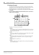
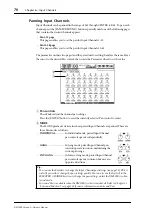
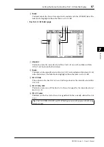
BUS ROUTING/FOLLOW PAN section
•
BUS ROUTING
............ This section enables you to select a destination Bus for the
selected channel. When the D button is turned on, the channel
signal is patched to the Direct Out selected in the parameter
box below the button.
•
FOLLOW PAN
............. This button determines whether the Input Channel’s Pan set-
ting is applied to the paired Bus Outs (Follow Pan function).
When the button is turned off, the Follow Pan function is dis-
abled and an identical signal is sent to the paired Bus Outs. In
surround mode, it also determines whether the Surround Pan
setting is applied to the Bus Outs.
D
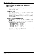
AUX section
•
AUX
............................... These controls set the currently-selected Input Channel’s Aux
Send 1–8 levels and positions. (See page 93 for more informa-
tion on Aux Sends.)
E
Meter section
•
Meters
............................ These meters indicate the levels of the currently-selected Input
Channel.
•
PRE EQ/PRE FADER/POST FADER
........... The metering position is displayed below
the meters.
F
GROUP section
•
FADER/MUTE/EQ/COMP
................These buttons indicate which Fader, Mute, EQ,
or Comp group, if any, the currently-selected
Input Channel is in. If the channel is in a group,
the group number appears. If the channel is not
in a group, “—” appears.
Summary of Contents for 006IPTO-F0
Page 42: ...42 Chapter 3 Operating Basics DM1000 Version 2 Owner s Manual ...
Page 52: ...52 Chapter 4 Connections and Setup DM1000 Version 2 Owner s Manual ...
Page 92: ...92 Chapter 7 Bus Outs DM1000 Version 2 Owner s Manual ...
Page 108: ...108 Chapter 8 Aux Sends DM1000 Version 2 Owner s Manual ...
Page 146: ...146 Chapter 11 Surround Functions DM1000 Version 2 Owner s Manual ...
Page 214: ...214 Chapter 16 Automix DM1000 Version 2 Owner s Manual ...
Page 385: ...DM1000 Block Diagram ...

