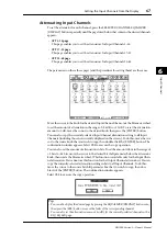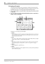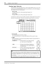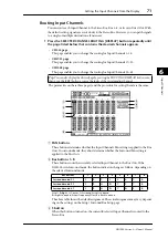
80
Chapter 6—Input Channels
DM1000 Version 2—Owner’s Manual
Using MS Stereo Microphone
The MS system is a type of stereo recording that uses two microphones; mono-directional
M (Middle) and bi-directional S (Side) microphones. An M microphone picks up main sig-
nals, and an S microphone picks up directional signals. These two signals are decoded by
calculating a sum (M plus S) and a difference (M minus S), and are recorded to L and R
channels.
An MS microphone is usually a stereo microphone that has both M and S functions. Use an
MS microphone in the following way:
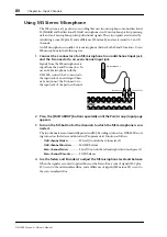
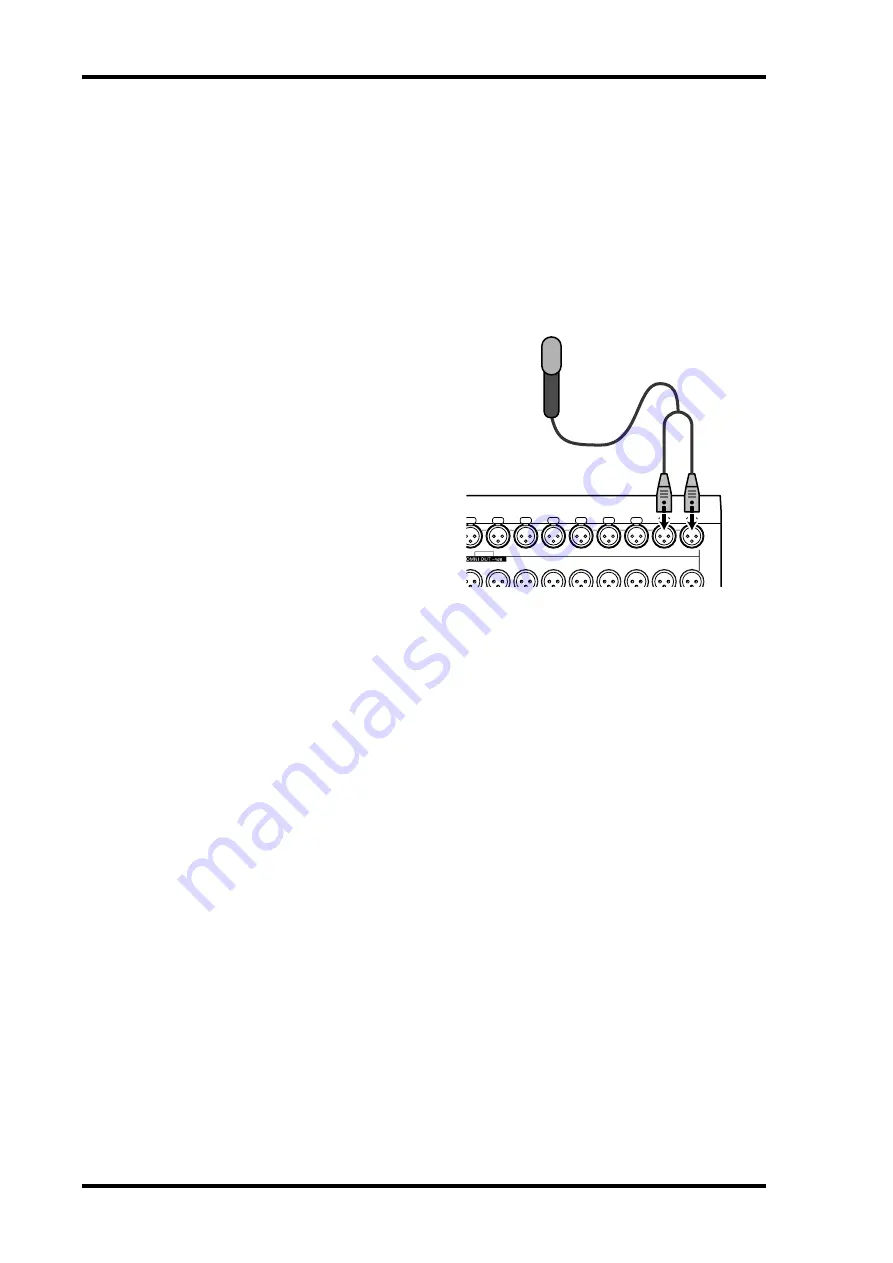
1 Connect the L connector of an MS microphone to an odd channel input jack,
and the R connector to an even channel input jack.
Signals from the MS microphone are
input from the L and R connectors. To
use an MS microphone with the
DM1000, connect the L connector to
the input jack of an odd Input Chan-
nel, and connect the R connector to
the input jack of the partner channel.
2 Press the [PAIR/GROUP] button repeatedly until the Pair/Group | Input page
appears.
3 Turn on the MS button for the channels to which the MS microphone is con-
nected.
The two channels are automatically paired and MS Decoding is turned on. With MS Decod-
ing turned on, the faders and Encoders (Pan parameters) function as follows:
•
Odd-channel faders
................M level (Controls the volume level.)
•
Odd-channel Encoders
...........ML/MR balance
•
Even-channel faders
................S level (Controls the left and right directional spread.)
•
Even-channel Encoders
..........SL/SR balance
4 Use the faders and Encoders to adjust the MS microphone level and balance.
When the signals are routed to paired Buses or the Stereo Bus, a sum of signals (ML plus
SL) is sent to the odd-numbered Bus, and a difference of signals (ML minus SL) is sent to
the even-numbered Bus.
INPUT
2
3
4
5
6
7
8
1
9
2
3
4
5
6
7
8
1
9
MS microphone
R connector
L connector
Summary of Contents for 006IPTO-F0
Page 42: ...42 Chapter 3 Operating Basics DM1000 Version 2 Owner s Manual ...
Page 52: ...52 Chapter 4 Connections and Setup DM1000 Version 2 Owner s Manual ...
Page 92: ...92 Chapter 7 Bus Outs DM1000 Version 2 Owner s Manual ...
Page 108: ...108 Chapter 8 Aux Sends DM1000 Version 2 Owner s Manual ...
Page 146: ...146 Chapter 11 Surround Functions DM1000 Version 2 Owner s Manual ...
Page 214: ...214 Chapter 16 Automix DM1000 Version 2 Owner s Manual ...
Page 385: ...DM1000 Block Diagram ...


