Display
29
01V—Owner’s Manual
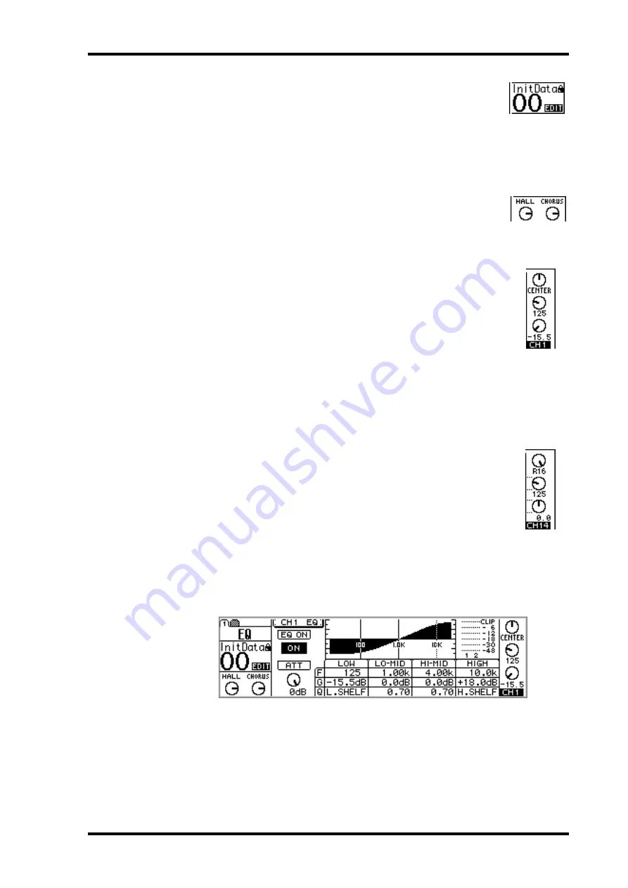
Memory
—This area of the display shows the number and title of the
selected scene memory, whether that scene memory is read only or write
protected (indicated by the closed padlock icon), and whether or not the
contents of the Edit Buffer have been edited. See “Scene Memory Dis-
play Area” on page 185 for more information. Also in the Memory area
are the MIDI and HOST indicators, which appear when MIDI data is
received at the MIDI IN or TO HOST port, respectively. See “MIDI
Receive Indicators” on page 224 for more information.
Effects Returns
—This area of the display shows two control icons,
which indicate the positions of the RETURN level controls, and the type
of effects selected for the two onboard effects processors: Effect 1 and
Effect 2. When the EFFECT 1 or EFFECT 2 Fader mode is selected, the
corresponding control icon is highlighted.
Selected channel
—This area of the display shows three control icons:
Pan, EQ frequency (F), and EQ gain (G), which indicate the pan, EQ fre-
quency, and EQ gain of the selected channel. Below these is the selected
channel indicator, showing which channel is currently selected. The fol-
lowing channels can be selected.
•
CH1 through CH24
—Input channels 1 through 24
•
ST
—Stereo output
•
RTN1, RTN2
—Effects returns 1 and 2
•
AUX1 through AUX4
—Aux sends 1 through 4
•
EFF1, EFF2
—Effects sends 1 and 2
•
1–16, MAS
—Remote function channels
When channels 13 through 16, the effects return channels, or paired input
channels from 1 through 12 are selected, dotted lines appear to the right
of these control icons when an odd or left channel is selected. Similarly,
dotted lines appear to the left, as shown here, when an even or right chan-
nel is selected.
Page area
—This area of the display is where the various setup, utility, and mixing
function pages appear. As well as showing parameter values numerically, faders and
rotary controls are represented graphically, so you can actually see pan and fader posi-
tions. See “Display Elements” on page 30 for more information. An example page is
shown below.
Summary of Contents for 01V
Page 18: ...8 Chapter 1 Welcome to the 01V 01V Owner s Manual ...
Page 22: ...12 Chapter 2 Getting Started 01V Owner s Manual ...
Page 36: ...26 Chapter 3 Touring the 01V 01V Owner s Manual ...
Page 48: ...38 Chapter 4 Getting Around the User Interface 01V Owner s Manual ...
Page 116: ...106 Chapter 9 Aux Sends 01V Owner s Manual ...
Page 124: ...114 Chapter 10 Bus Outs 01V Owner s Manual ...
Page 170: ...160 Chapter 12 Effects 01V Owner s Manual ...
Page 192: ...182 Chapter 13 Dynamics Processors 01V Owner s Manual ...
Page 262: ...252 Chapter 18 System Examples 01V Owner s Manual ...
Page 270: ...260 Appendix A General 01V Owner s Manual ...
Page 282: ...272 Appendix B Specifications 01V Owner s Manual ...
Page 302: ...292 Appendix D Resources 01V Owner s Manual ...


