32
Bus Outs
01V96i—Reference Manual
■
Viewing Faders and Other
Parameters
To display the View | Fader page, use the corresponding [SEL]
button to select the desired bus, then press the DISPLAY
ACCESS [VIEW] button, then press the [F2] button.
The Fader page layouts for Stereo Out and Bus Out 1–8 are
slightly different.
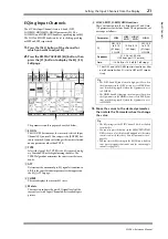
Stereo Out Fader page
1
BAL
This control adjusts the level balance between the L and R
channels of the Stereo Out.
2
ON/OFF
This button turns the Stereo Out on or off, and links with
the [ON] button in the STEREO section.
3
Fader
This fader adjusts the Stereo Out output levels, and links
with the [STEREO] fader. The fader knob is highlighted
when the fader is set to 0.0 dB.
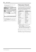
Bus Out (1–8) Fader page
1
BUS ON/OFF
This button turns the currently-selected Bus Out (1–8)
on or off, and links with the [ON] (9–16) button in the
Master layer.
2
BUS Fader
This fader sets the currently-selected Bus Out (1–8) level,
and links with the fader (9–16) in the Master layer. The
fader knob is highlighted when the fader is set to 0.0 dB.
3
TO ST PAN
This control sets the Bus Out to Stereo Out Pan position
for the currently-selected Bus Out (1–8).
4
TO ST ON/OFF
This button turns on or off the Bus Out to Stereo Out sig-
nal for the currently-selected Bus Out (1–8).
5
TO ST Fader
This fader sets the Bus Out to Stereo Out signal level for
the currently-selected Bus Out (1–8).
1
3
2
Tip:
The TO ST PAN, ON/OFF, and TO ST Fader parameters
also appear on the Pan/Route | Bus to St page.
1 2
4
3
5

