


01V96i Quick Start Guide
25/32
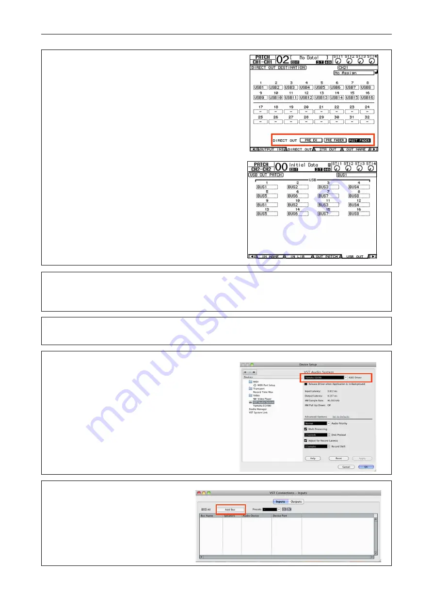
Note:
For Direct Out recording, you may also choose the posi-
tion from which the audio signals are sent, e.g PRE EQ (record-
ing is unaffected by EQ, Dynamics and fader adjustments) or
POST FADER (EQ, Dynamics and fader edits affect the record-
ing). To change the setting, press the PATCH key to access the
DIRECT OUT page.
Note:
For Bus Out recording, confirm that the Buses required
for recording are patched to USB OUT. Press the PATCH key to
access the USB OUT page and confirm if USB1 set to BUS1,
USB2 set to BUS2 respectively.
3.
Activate the audio signals from the mics or audio sources. Press the HOME(METER) key to open the Meter
page and check the level meter for each input channel (and Bus Outs in case of Bus Out recording). Adjust the
gain to avoid clipping, and set the fader to nominal (0dB) level.
4.
For Bus Out recording, press the MASTER key to show the MASTER Layer and press the SOLO key of BUS 1
& 2 to check the level balance between them.
5.
Startup Cubase AI, open Device Setup in the Devices
menu and set the driver to Yamaha Steinberg USB
ASIO (Yamaha 01V96i) in the VST Audio System sec-
tion.
6.
Open VST Connections in the Device
menu, and add the necessary number of
recording buses (Mono or Stereo) for
recording.
Summary of Contents for 01V96i
Page 1: ...2nd Edition...


