130
Chapter 11—Common Channel Functions
02R96 Version 2—Owner’s Manual
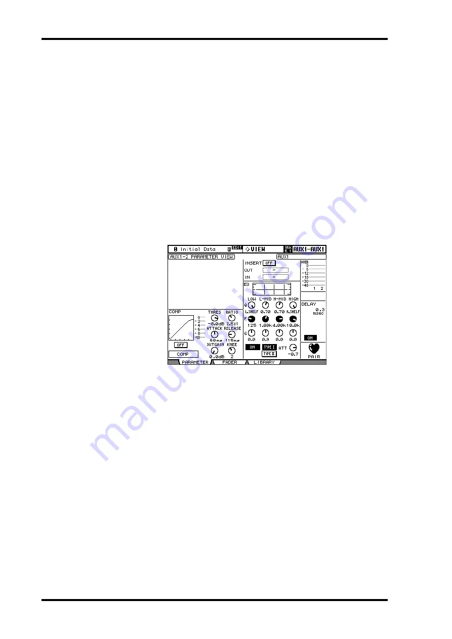
EQ:
The currently selected channel’s EQ and Attenuator can be set. Also displayed is the EQ
curve of the currently selected Input Channel. See “Using EQ” on page 111 for more infor-
mation.
Meters:
These meters indicate the levels of the currently selected channel and its horizon-
tal or vertical partner.
Phase:
The signal phase of the currently selected Input Channel can be reversed. See
“Reversing the Signal Phase” on page 73 for more information.
DELAY:
The currently selected channel’s Delay function can be set. See “Delaying Channel
Signals” on page 120 for more information.
PAIR:
This heart icon indicates whether or not channels are paired. See “Pairing Channels”
on page 123 for more information.
Output Channels
This is the Parameter View page for the Bus Outs, Aux Sends, and the Stereo Out. Parame-
ters are the same as for the Input Channel Parameter View page, minus the GATE and Phase
sections and the DELAY MIX and FB GAIN parameters. The parameter settings of the left
and right channels of the Stereo Out can be viewed individually. Use the [SEL] buttons to
toggle between the left and right channels.
Viewing Channel Fader Settings
The fader-related settings of the currently selected Input Channel, Bus Out, Aux Send, or
the Stereo Out can be viewed and set on the Fader View pages.
1
Use the DISPLAY ACCESS [VIEW] button to select the Fader View page.
2
Use the LAYER buttons to select Layers, and use the [SEL] buttons to select
channels.
3
Use the cursor buttons to select the parameters, and use the Parameter
wheel, INC/DEC buttons, and [ENTER] buttons to set them.
Pan and Balance controls can be set to center by pressing [ENTER] while they’re selected.


