61U5H11
7-32
9
8
7
6
5
4
3
2
1
Clamp bracket and swivel bracket
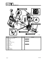
Installing the PTT unit (ET)
1.
Fully tilt the outboard motor up, and then
support it with the tilt stop lever
1
.
w
9
When installing the PTT unit without
removing the power unit, be sure to sus-
pend the outboard motor. Otherwise, the
outboard motor could suddenly fall and
result in injury.
9
After tilting the outboard motor up, be
sure to support it with the tilt stop lever.
2.
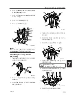
Lift the PTT unit up, install the lower
mounting shaft
2
and then tighten the
bolts
3
.
3.
Install the tilt ram upper end into the swiv-
el bracket with the pin
4
and circlip
5
.
4.
Tighten the self-locking nut
6
to the
specified torque.
5.
Install the anode
7
.
6.
Pass the PTT motor lead
8
through the
hole of the port clamp bracket.
7.
Fasten the PTT motor lead and trim sen-
sor lead with the lock ties
9
.
8.
Inject grease into all grease nipples until
grease comes out from the bushings
a
.
61U70280
1
6
5
7
3
9
8
4
2
3
6G470770
a
Self-locking nut
6
:
15 N·m (1.5 kgf·m, 11.1 ft·lb)
6G470720
1
61U5H11_07_1 06.2.13 1:24 PM Page 35
Summary of Contents for 115B
Page 1: ...115B SERVICE MANUAL 61U 28197 5H 11 140B E115A E115A 115B 140B ...
Page 4: ......
Page 79: ...61U5H11 4 18 9 8 7 6 5 4 3 2 1 MEMO ...
Page 136: ...POWR 5 55 61U5H11 Power unit MEMO ...
Page 159: ...61U5H11 6 22 9 8 7 6 5 4 3 2 1 Shimming Shimming 6G46090E T3 M3 M4 M1 M2 T1 T2 F R P ...
Page 255: ......


