61U5H11
8-16
9
8
7
6
5
4
3
2
1
Starter motor (WH, E, ET)/Charging system
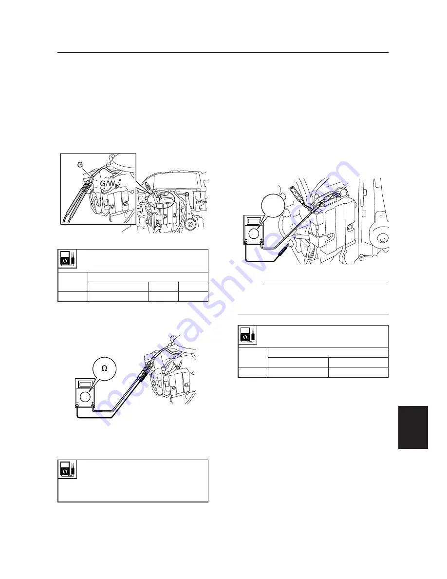
Checking the Rectifier Regulator
1.
Disconnect the Rectifier Regulator (R)
connector, then connect the digital circuit
tester to Rectifier Regulator (R) connec-
tor and ground
2.
Measure the Rectifier Regulator output
peak voltage. If less than specification,
measure the lighting coil output peak
voltage. Replace the Rectifier Regulator if
the output peak voltage of the lighting coil
is more than specification.
NOTE:
Do not use the peak voltage adaptor when
measuring the output peak voltage of the
Rectifier Regulator.
Rectifier Regulator output peak voltage:
Red (R) – Ground (B)
r/min
Unloaded
1,500
3,500
DC V
13
13
Charging system
Checking the lighting coil
1.
Disconnect the lighting coil connector.
2.
Connect the probe to the lighting coil.
3.
Measure the lighting coil output peak
voltage. Replace the stator assembly if
less than specification.
4.
Connect the digital circuit tester to the
lighting coil connector.
5.
Measure the lighting coil resistance.
Replace the stator assembly if out of
specification.
61U80050
Lighting coil resistance
(reference data):
Green(G) – Green/white (G/W)
0.36–0.54
Ω
at 20°C (68°F)
R
61U80040
DCV
Lighting coil output peak voltage:
Green (G) – Green/white (G/W)
r/min
Unloaded
Cranking
1,500
3,500
DC V
8.0
31.0
72.0
61U80170
61U5H11_08 06.6.9 18:47 Page 17
Summary of Contents for 115B
Page 1: ...115B SERVICE MANUAL 61U 28197 5H 11 140B E115A E115A 115B 140B ...
Page 4: ......
Page 79: ...61U5H11 4 18 9 8 7 6 5 4 3 2 1 MEMO ...
Page 136: ...POWR 5 55 61U5H11 Power unit MEMO ...
Page 159: ...61U5H11 6 22 9 8 7 6 5 4 3 2 1 Shimming Shimming 6G46090E T3 M3 M4 M1 M2 T1 T2 F R P ...
Page 255: ......


