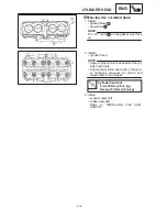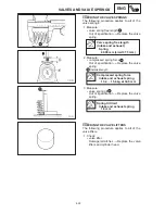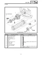
4-29
CYLINDER AND PISTON
ENG
b
1
2
4
5
3
a
NOTE:
NOTE:
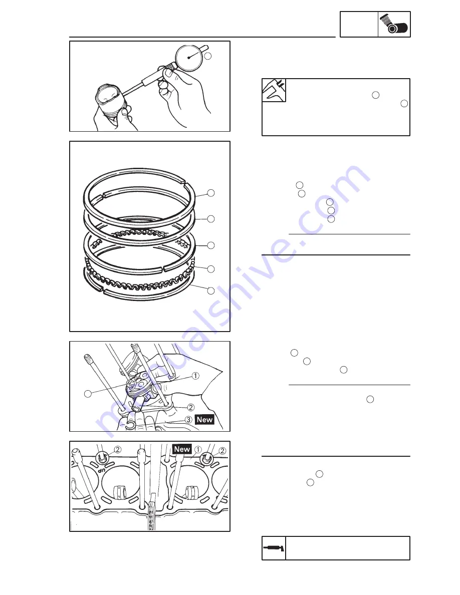
3. Calculate:
piston-pin-to-piston clearance
Out of specification
Replace the piston
pin.
Piston-pin-to-piston clearance =
Piston pin bore size
b
–
Piston pin outside diameter
a
Piston-pin-to-piston clearance
0.011
0.013 mm
<Limit>: 0.023 mm
EB404701
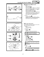
INSTALLING THE PISTON AND CYLINDER
The following procedure applies to all of the pis-
tons and cylinders.
1. Install:
top ring
1
2nd ring
2
lower oil ring rail
3
upper oil ring rail
4
oil ring expander
5
Be sure to install the piston rings so that the
manufacturer’s marks or numbers face up.
2. Install:
piston
1
piston pin
2
piston pin clip (New)
3
Apply engine oil onto the piston pin.
Make sure that the “EX” mark
a
on the pis-
ton faces towards the exhaust side of the
engine.
Before installing the piston pin clip, cover
the crankcase opening with a clean rag to
prevent the clip from falling into the crank-
case.
3. Install:
gasket (New)
1
dowel pins
2
4. Lubricate:
piston
piston rings
cylinder
(with the recommended lubricant)
Recommended lubricant
Engine oil
Summary of Contents for 1998 FZS600 5DM1-AE1
Page 1: ......
Page 2: ......
Page 8: ......
Page 9: ...GEN INFO 1 ...
Page 11: ...GEN INFO ...
Page 20: ...SPEC 2 ...
Page 22: ...SPEC ...
Page 46: ...2 24 1 2 LUBRICATION DIAGRAMS SPEC 1 Camshaft 2 Crankshaft ...
Page 54: ...SPEC ...
Page 55: ...CHK ADJ 3 ...
Page 57: ...CHK ADJ ...
Page 109: ...CHK ADJ ...
Page 110: ...ENG 4 ...
Page 189: ...COOL 5 ...
Page 191: ...COOL ...
Page 202: ...CARB 6 ...
Page 204: ...CARB ...
Page 216: ...6 12 CARB ...
Page 217: ...CHAS 7 ...
Page 288: ...ELEC 8 ...
Page 290: ...ELEC ...
Page 292: ...8 2 CIRCUIT DIAGRAM ELEC CIRCUIT DIAGRAM ...
Page 326: ...8 36 SIGNAL SYSTEM ELEC EB806000 SIGNAL SYSTEM CIRCUIT DIAGRAM ...
Page 355: ...TRBL SHTG 9 ...
Page 357: ...TRBL SHTG ...
Page 363: ...TRBL SHTG ...


