2-28
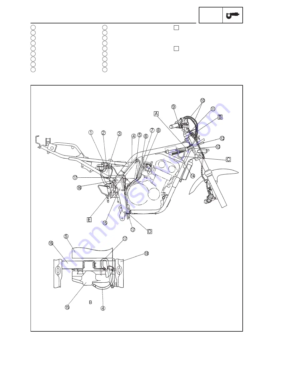
1 Battery negative (–) lead
2 Rear brake switch lead
3 Battery
4 Reservoir tank hose
5 Air filter
6 Fuel tank breather hose
7 Fuel tank drain hose
8 T.P.S. lead
9 Handlebar switch lead (right)
CABLE ROUTING
SPEC
10
Throttle cable
11
Brake hose
12
Headlight lead
13
Speed sensor lead
14
Main switch lead
15
Reservoir tank
16
Cross tube
17
Reservoir tank over flow hose
18
Swingarm bracket
A Use a plastic clamp to fasten
together the throttle cables,
headlight lead handlebar switch
(right) and speed sensor lead.
B Use a plastic locking tie to
fasten the handlebar switch
(right) and brake hose to the
right front fork inner tube.
Summary of Contents for 1998 FZS600 5DM1-AE1
Page 1: ......
Page 2: ......
Page 8: ......
Page 9: ...GEN INFO 1 ...
Page 11: ...GEN INFO ...
Page 20: ...SPEC 2 ...
Page 22: ...SPEC ...
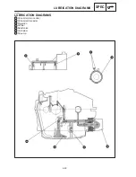
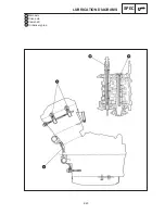
Page 46: ...2 24 1 2 LUBRICATION DIAGRAMS SPEC 1 Camshaft 2 Crankshaft ...
Page 54: ...SPEC ...
Page 55: ...CHK ADJ 3 ...
Page 57: ...CHK ADJ ...
Page 109: ...CHK ADJ ...
Page 110: ...ENG 4 ...
Page 189: ...COOL 5 ...
Page 191: ...COOL ...
Page 202: ...CARB 6 ...
Page 204: ...CARB ...
Page 216: ...6 12 CARB ...
Page 217: ...CHAS 7 ...
Page 288: ...ELEC 8 ...
Page 290: ...ELEC ...
Page 292: ...8 2 CIRCUIT DIAGRAM ELEC CIRCUIT DIAGRAM ...
Page 326: ...8 36 SIGNAL SYSTEM ELEC EB806000 SIGNAL SYSTEM CIRCUIT DIAGRAM ...
Page 355: ...TRBL SHTG 9 ...
Page 357: ...TRBL SHTG ...
Page 363: ...TRBL SHTG ...


