17
Tyros2
NITOR SPEAKER
RS-MS02
ER’S MANUAL
ENUNGSANLEITUNG
E D’EMPLOI
9.
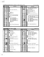
CK Circuit Board
(Time required: About 4 minutes)
9-1
Separate the unit into the upper case assembly and the
lower case assembly. (See procedure 1.)
9-2
Remove the four (4) screws marked [530H]. The CK
circuit board can then be removed. (Fig.5)
10.
SPOL Circuit Board
(Time required: About 4 minutes)
10-1
Separate the unit into the upper case assembly and the
lower case assembly. (See procedure 1.)
10-2
Remove the two (2) screw marked [540D]. The SPOL
circuit board can then be removed. (Fig.4)
11.
SPOR Circuit Board
(Time required: About 4 minutes)
11-1
Separate the unit into the upper case assembly and the
lower case assembly. (See procedure 1.)
11-2
Remove the two (2) screw marked [540E]. The SPOR
circuit board can then be removed. (Fig.4)
12.
HP Circuit Board
(Time required: About 4 minutes)
12-1
Separate the unit into the upper case assembly and the
lower case assembly. (See procedure 1.)
12-2
Remove the three (3) screws marked [530H]. The HP
circuit board can then be removed. (Fig.5)
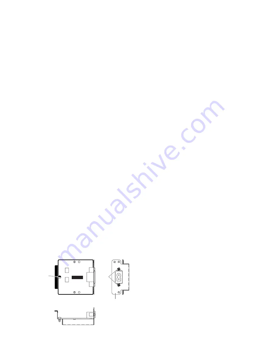
[530]
Inlet Upper Box
[540]
INLET
(Fig.6)
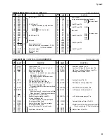
6.
Power Supply Unit
(Time required: About 6 minutes)
6-1
Separate the unit into the upper case assembly and the
lower case assembly. (See procedure 1.)
6-2
Remove the three (3) screws marked [140A] and the
screw marked [150]. The AC upper frame assembly can
then be removed. (Fig.3)
6-3
Remove the six (6) screws marked [530D]. The power
supply unit can then be removed. (Fig.4)
7.
AJK Circuit Board
(Time required: About 6 minutes)
7-1
Separate the unit into the upper case assembly and the
lower case assembly. (See procedure 1.)
7-2
Remove the four (4) screws marked [530A]. The AC
lower frame cover assembly can then be removed.
(Fig.4)
7-3
Remove the knob(MIC.TRIM) marked [150]. (Fig.4)
7-4
Remove the four (4) screws marked [530B] and the six
(6) screws marked [540B]. The AJK circuit board can
then be removed. (Fig.4)
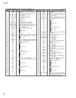
8.
INLET Circuit Board
(Time required: About 6 minutes)
8-1
Separate the unit into the upper case assembly and the
lower case assembly. (See procedure 1.)
8-2
Remove the two (2) screws marked [140B]. The inlet
lower box can then be removed. (Fig.3,Fig.4)
8-3
Remove the two (2) screws marked [530C] and the three
(3) screws marked [540C]. The inlet upper box can then
be removed. (Fig.4)
8-4
Remove the screw marked [530] and the two (2) screws
marked [540]. The INLET circuit board can then be
removed. (Fig.6)
*
When installing the inlet upper box, tighten the three (3)
screws marked [540C] first, and then tighten the two (2)
screws marked [530C]. (Fig.4)


