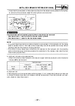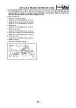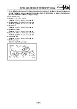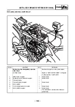
– 86 –
CHAS
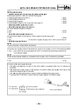
• [B-5] ABS malfunction check using the ABS self-diagnosis (present malfunction)
NOTE:
_
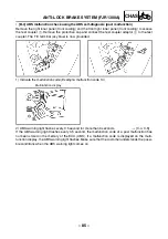
Before proceeding, read [B-3], “Function of the test coupler terminals”.
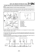
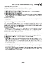
Remove the right inner panel (front cowling) and the front right inner panel to access the test cou-
pler. Remove the protective cap and connect the test coupler adaptor to the test coupler. The T/C
terminal (sky blue) is now grounded. (Figure
È
)
Because malfunction codes for present malfunctions are not displayed on the meter assembly,
check the malfunction code as follows.
Set the pocket tester range to DC 20 V. Connect the pocket tester negative probe to the T/F termi-
nal (light green) of the test coupler adaptor and the pocket tester positive probe to the positive bat-
tery terminal. (Figure
É
)
Determine the malfunction code according to the movement of the pocket tester needle. (Figure
Ê
)
A tester reading with the digits of 10 and digits of 1 pattern is shown below.
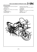
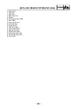
1
Test coupler
2
Lock plate
3
Protective cap
4
Grounding
5
T/C terminal
6
T/F terminal
7
Light terminal
8
Test coupler adaptor
È
É
É
É
É
(light green)
(light green)
(white
/red)
(black)
(white/red)
Ê
Example: malfunction code 12
Example: malfunction code 21
Time
(second)
ANTI-LOCK BRAKE SYSTEM (FJR1300A)
Summary of Contents for 2003 FJR1300
Page 1: ...2003 FJR1300 R FJR1300A R 5JW1 AE4 SUPPLEMENTARY SERVICE MANUAL ...
Page 2: ......
Page 159: ......
Page 160: ...YAMAHA MOTOR CO LTD 2500 SHINGAI IWATA SHIZUOKA JAPAN ...

