7 - 19
DRIV
3
1
4
6
5
1
2
T
R
.
.
70 Nm (7.0m
•
kg, 51 ft
•
Ib)
LS
LS
LS
Order
Job/Part
Q’ty
Remarks
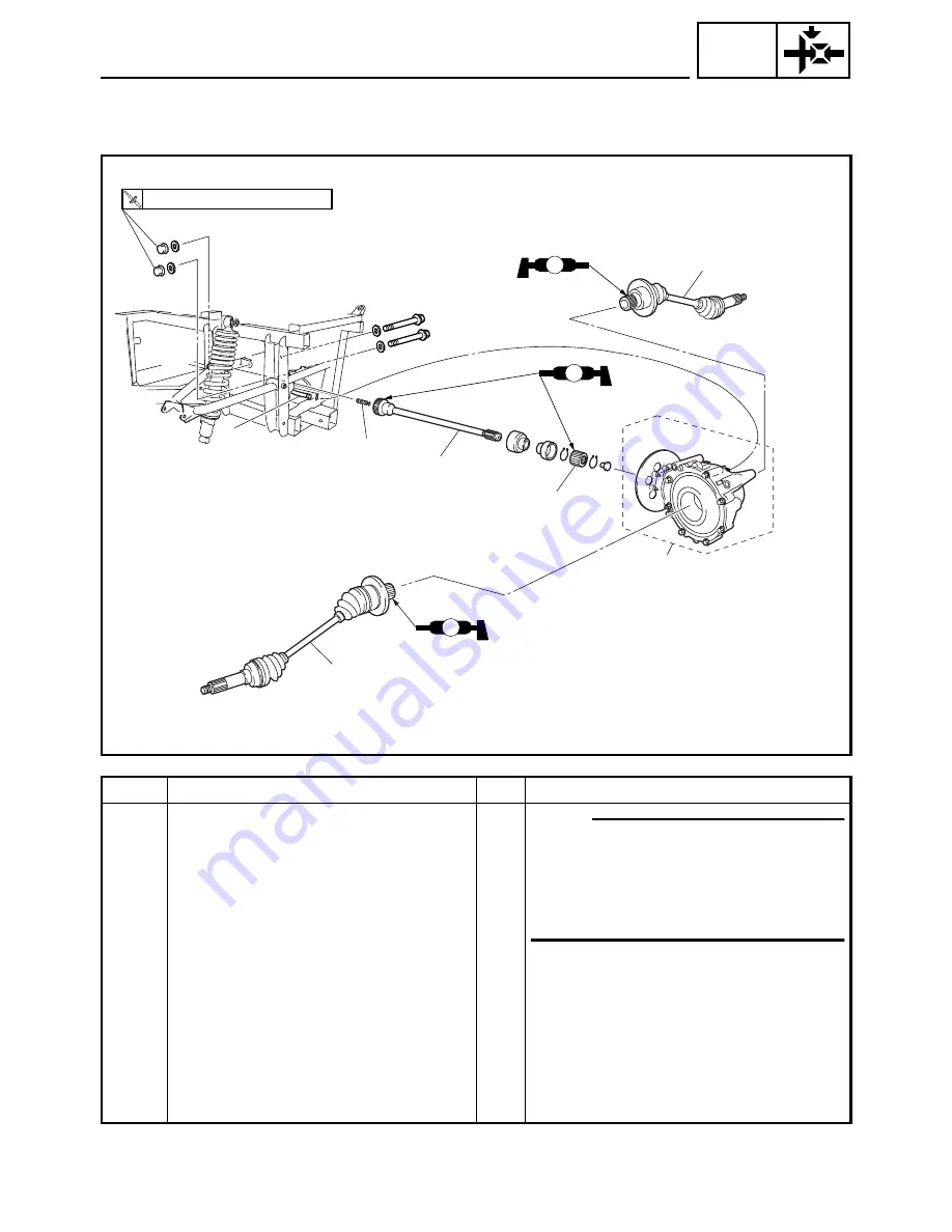
1
Rear constant velocity joint
2
NOTE:
Remove the constant velocity joint on the
right side of the vehicle, rotate the final
gear assembly slightly so that the con-
stant velocity joint on the left side clears
the frame, and then remove it.
2
Final drive gear case breather hose
1
Disconnect.
3
Final drive gear assembly
1
4
Compression spring
1
5
Coupling gear
1
6
Drive shaft
1
For installation, reverse the removal pro-
cedure.
REAR CONSTANT VELOCITY JOINTS, FINAL DRIVE
GEAR AND DRIVE SHAFT
Summary of Contents for 2004 Rhino 660 YXR660FAS
Page 1: ...LIT 11616 17 23 5UG F8197 10 YXR660FAS SERVICE MANUAL ...
Page 6: ......
Page 40: ...2 11 SPEC ENGINE SPECIFICATIONS Cylinder head tightening sequence ...
Page 55: ...2 26 SPEC COOLANT FLOW DIAGRAMS 1 Coolant outlet hose 2 Radiator inlet pipe 2 1 ...
Page 383: ...9 31 ELEC LIGHTING SYSTEM ...
Page 418: ......
Page 419: ......
Page 420: ...YAMAHA MOTOR CO LTD 2500 SHINGAI IWATA SHIZUOKA JAPAN PRINTED IN U S A ...


