4 - 59
CHAS
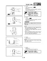
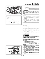
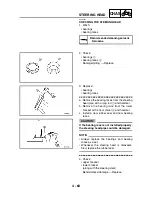
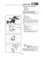
9. Install:
• right handlebar switch
1
WARNING
_
Make sure the throttle grip operates
smoothly.
NOTE:
_
Align the projection
a
on the right handlebar
switch with the hole
b
in the handlebar.
1
b
a
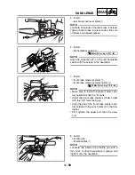
10.Install:
• grip end (left)
NOTE:
There should be 1 ~ 3 mm (0.04 ~ 0.12 in) of
clearance
a
between the throttle grip and the
grip end.
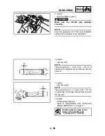
11.Install:
• grip end (right)
NOTE:
There should be 2.4 ~ 4.4 mm (0.09 ~ 0.17 in)
of clearance
a
between the throttle grip and
the grip end.
12.Adjust:
• throttle cable free play
Refer to “ADJUSTING THE THROTTLE
CABLE FREE PLAY” in chapter 3.
Throttle cable free play (at the
flange of the throttle grip)
3 ~ 5 mm (0.12 ~ 0.20 in)
HANDLEBAR
Summary of Contents for 2004 YP400
Page 1: ...2004 YP400 S 5RU1 AE1 SERVICE MANUAL ...
Page 2: ......
Page 8: ......
Page 9: ...GEN INFO 1 ...
Page 11: ...GEN INFO ...
Page 28: ...SPEC 2 ...
Page 30: ...SPEC ...
Page 77: ...CHK ADJ 3 ...
Page 137: ......
Page 138: ...CHAS 4 ...
Page 210: ......
Page 211: ...ENG 5 ...
Page 286: ...COOL 6 ...
Page 288: ...COOL ...
Page 299: ...FI 7 ...
Page 301: ...FI ...
Page 342: ...ELEC 8 ...
Page 378: ...8 34 ELEC LIGHTING SYSTEM ...
Page 404: ......
Page 405: ...TRBL SHTG 9 ...
Page 415: ......
Page 416: ...YAMAHA MOTOR CO LTD 2500 SHINGAI IWATA SHIZUOKA JAPAN ...


