5 - 16
ENG
CAMSHAFTS
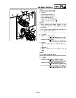
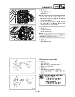
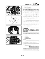
8. Turn:
• crankshaft
(turn the primary sheave nut on the left side
of the crankshaft several turns counter-
clockwise)
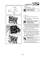
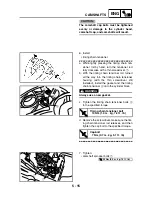
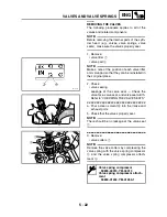
9. Check:
• “I” mark
Make sure the “I” mark on the generator
rotor is aligned with the stationary pointer
on the generator rotor cover.
• camshaft sprocket punch marks
Make sure the punch marks on the cam-
shaft sprockets are aligned with the cylinder
head mating surface.
Out of alignment
→
Adjust.
Refer to the installation steps above.
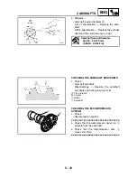
10.Measure:
• valve clearance
Out of specification
→
Adjust.
Refer to “ADJUSTING THE VALVE
CLEARANCE” in chapter 3.
Summary of Contents for 2004 YP400
Page 1: ...2004 YP400 S 5RU1 AE1 SERVICE MANUAL ...
Page 2: ......
Page 8: ......
Page 9: ...GEN INFO 1 ...
Page 11: ...GEN INFO ...
Page 28: ...SPEC 2 ...
Page 30: ...SPEC ...
Page 77: ...CHK ADJ 3 ...
Page 137: ......
Page 138: ...CHAS 4 ...
Page 210: ......
Page 211: ...ENG 5 ...
Page 286: ...COOL 6 ...
Page 288: ...COOL ...
Page 299: ...FI 7 ...
Page 301: ...FI ...
Page 342: ...ELEC 8 ...
Page 378: ...8 34 ELEC LIGHTING SYSTEM ...
Page 404: ......
Page 405: ...TRBL SHTG 9 ...
Page 415: ......
Page 416: ...YAMAHA MOTOR CO LTD 2500 SHINGAI IWATA SHIZUOKA JAPAN ...

