8 - 41
–
+
ELEC
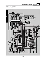
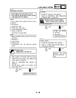
SIGNALING SYSTEM
YES
NO
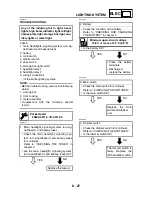
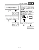
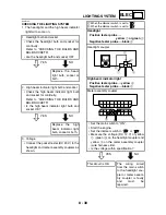
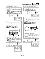
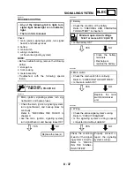
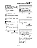
4. The V-belt replacement indicator fails to
come on.
YES
NO
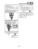
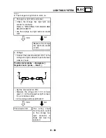
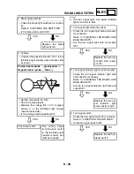
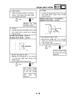
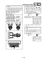
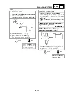
7. Voltage
• Connect the pocket tester (DC 20 V) to the
turn signal light coupler or meter assembly
coupler (wire harness side) as shown.
È
Front turn signal light assembly (left)
É
Front turn signal light assembly (right)
Ê
Tail/brake light assembly
Ë
Meter assembly
Left turn signal light
Positive tester probe
→
chocolate
1
Negative tester probe
→
ground
Right turn signal light
Positive tester probe
→
dark green
2
Negative tester probe
→
ground
B
L
Ch
B
L
Ch
B
L
Dg
B
L
Dg
1
2
È
É
G
/
L
L
Y
/
L B
/
L Gy
B
Ch Dg
Y
R
/
W R
/
G G
2
1
Ë
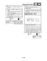
• Set the main switch to “ON”.
• Set the turn signal switch to “
” or “
”.
• Measure the voltage (DC 12 V) of the
chocolate
1
or dark green
2
at the turn
signal light coupler or meter assembly
coupler (wire harness side).
• Is the voltage within specification?
This circuit is OK.
The
wiring
circuit
from the turn signal
switch to the turn sig-
nal light coupler or
meter assembly cou-
pler is faulty and
must be repaired.
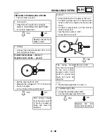
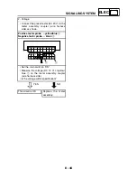
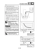
1. V-belt replacement indicator bulb and
socket
• Check the V-belt replacement indicator
bulb and socket for continuity.
• Are the V-belt replacement indicator bulb
and socket OK?
Replace the V-belt
replacement indica-
tor bulb, socket or
both.
L
/
R
Dg
B
Ch
Br
Dg
B
Ch
2
1
Ê
Summary of Contents for 2004 YP400
Page 1: ...2004 YP400 S 5RU1 AE1 SERVICE MANUAL ...
Page 2: ......
Page 8: ......
Page 9: ...GEN INFO 1 ...
Page 11: ...GEN INFO ...
Page 28: ...SPEC 2 ...
Page 30: ...SPEC ...
Page 77: ...CHK ADJ 3 ...
Page 137: ......
Page 138: ...CHAS 4 ...
Page 210: ......
Page 211: ...ENG 5 ...
Page 286: ...COOL 6 ...
Page 288: ...COOL ...
Page 299: ...FI 7 ...
Page 301: ...FI ...
Page 342: ...ELEC 8 ...
Page 378: ...8 34 ELEC LIGHTING SYSTEM ...
Page 404: ......
Page 405: ...TRBL SHTG 9 ...
Page 415: ......
Page 416: ...YAMAHA MOTOR CO LTD 2500 SHINGAI IWATA SHIZUOKA JAPAN ...

